
Hinge for a panel door, in particular for a cooling cupboard

A panel and hinge technology, applied in the hinge field, can solve the problems of deterioration during use, unsatisfactory sealing, etc.

Inactive Publication Date: 2012-07-11
ESTEM
View PDF10 Cites 4 Cited by
  • Summary
  • Abstract
  • Description
  • Claims
  • Application Information

AI Technical Summary

Problems solved by technology

[0004] One problem that has been noted with such hinges during heavy duty use, particularly when the panel door is made of a relatively heavy material such as glass for example, is that the closure is unsatisfactory and deteriorates during use.
Furthermore, this hinge is not optimal for uses other than those described in the prior art

Method used


Image

  • Hinge for a panel door, in particular for a cooling cupboard
  • Hinge for a panel door, in particular for a cooling cupboard
  • Hinge for a panel door, in particular for a cooling cupboard

Examples


Embodiment Construction

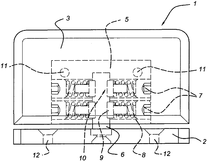
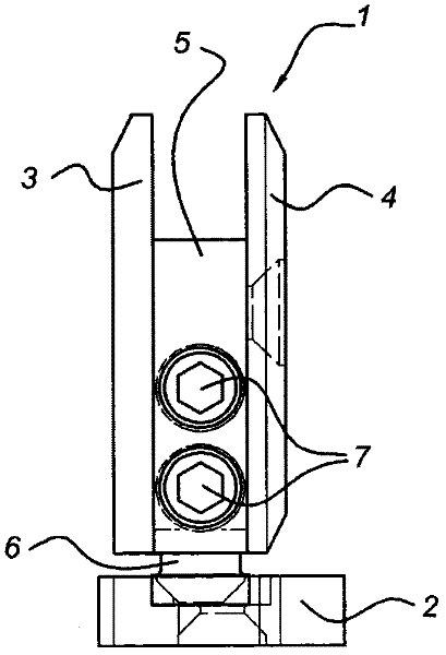
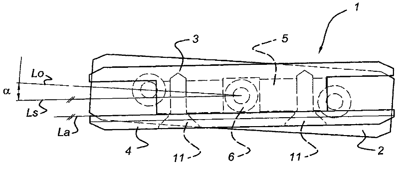
[0026] figure 1 A front view of an embodiment of a hinge 1 for a panel such as a glass door is shown. figure 2 shown in side view figure 1 the hinge, and image 3 shown in top view figure 1 hinge. It should be clear that such a hinge can have many embodiments, as shown in the prior art mentioned above, which will not be enumerated. exist Figure 1-3 In the embodiment shown, the hinge 1 has a sill / lintel attachment 2 which is attachable to a fixed enclosure, which in many cases is a sill or lintel. Two holes 12 are provided in the sill / lintel attachment 2 , here in the form of a plate, through which the sill / lintel attachment 2 can be attached to the lintel or sill, for example by screws.

[0027] Furthermore, the hinge 1 also has two clamping parts 3 and 4 which in this case are connected to each other. Panels such as glass panels may be clamped between these clamps. In this case, the clips are connected to each other by bolts 11 , for example countersunk screws formi...


PUM


Abstract

Hinge for a panel door, in particular a glass door, for sealing a space, such as a cooling cupboard, wherein the hinge (1) includes a sill / lintel-attachment part (2), two mutually connectable clamping parts (3, 4) for clamping a panel (21) in between them along an edge of the panel (21), a pivot pin (6) which connects, on one side, to the sill / lintel-attachment part (2) and, on the other side, to the clamping parts (3, 4) in such a manner that they can pivot with respect to one another, and tensioning parts (7, 8, 9) which force the sill / lintel-attachment part (2) into a neutral position with respect to the clamping parts (3, 4), wherein, in the neutral position, a mirror plane (Ls) of the clamping parts (3, 4) and a longitudinal axis (Lo) of the sill / lintel-attachment part (2) are at an angle of 5-15 degrees.

Description

technical field [0001] The present invention relates to a hinge for panel doors, in particular glass doors, especially in cooling cabinets. Background technique [0002] Such hinges are generally known. For example, US 5297313 describes a first embodiment of such a hinge. In this case, a compression spring on the pivot pin exerts a force on the pivot pin which forces the pivot pin into an intermediate position in which the longitudinal axis of the attachment plate and the plane of the clamping plate for the panel keep parallel. US 6161255 shows a variation of this where the pivot pin is provided with a recess so that the door has various "indexed positions", ie positions for the door to hold in place. US 6519811 describes a variant in which the force of the compression spring is transferred through a roller, the longitudinal axis of which is arranged parallel to the pivot pin. [0003] US 6966150 describes a variant that is provided with an adjusting screw to facilitate ...

Claims


Application Information

Patent Timeline
Patent Type & Authority Applications(China)
IPC IPC(8): E05D3/02E05D11/02E05D9/00
CPCE05D11/1064E05Y2800/74E05D7/08E05F1/1261E05Y2800/12E05Y2900/202E05D7/081E05D2011/1092E05Y2800/27E05D5/0246E05D11/1014E05F1/1253E05Y2800/21
Inventor 依文特·博乌曼
Owner ESTEM
Learn More