Flashlight capable of focusing automatically

An automatic focusing and flashlight technology, applied in the field of flashlights, can solve problems such as unsatisfactory focusing effects and inability to realize automatic adjustment, and achieve ideal results

Inactive Publication Date: 2012-07-11
徐永伟
View PDF7 Cites 16 Cited by
  • Summary
  • Abstract
  • Description
  • Claims
  • Application Information

AI Technical Summary

Problems solved by technology

However, during the focusing process of this type of flashlight, it is generally necessary to manually rotate the lamp base to change the distance between the focusing lens and the luminous body. Springs are generally arranged inside the lamp base, which cannot be automatically adjusted, and the focusing effect is not ideal.

Method used


Image

  • Flashlight capable of focusing automatically
  • Flashlight capable of focusing automatically
  • Flashlight capable of focusing automatically

Examples


Embodiment 1

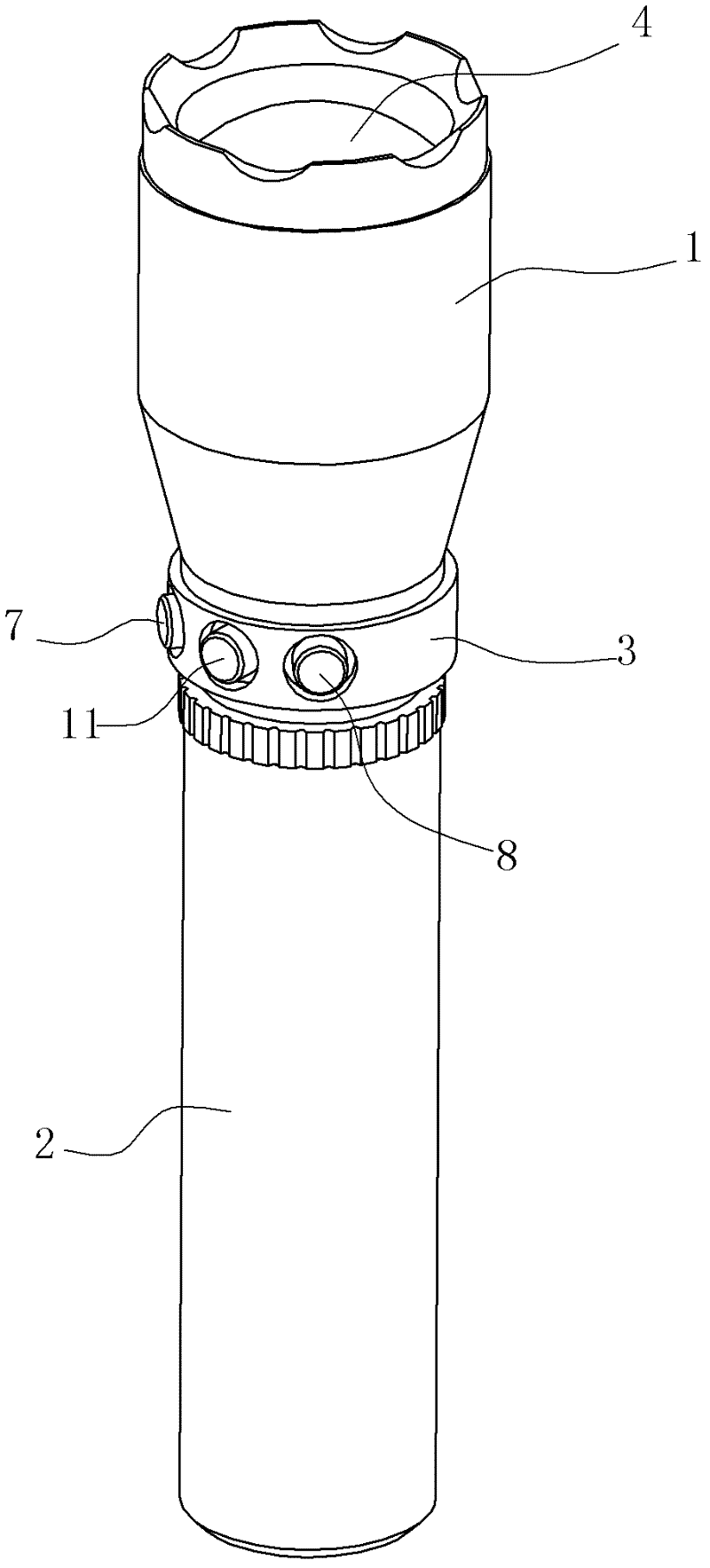
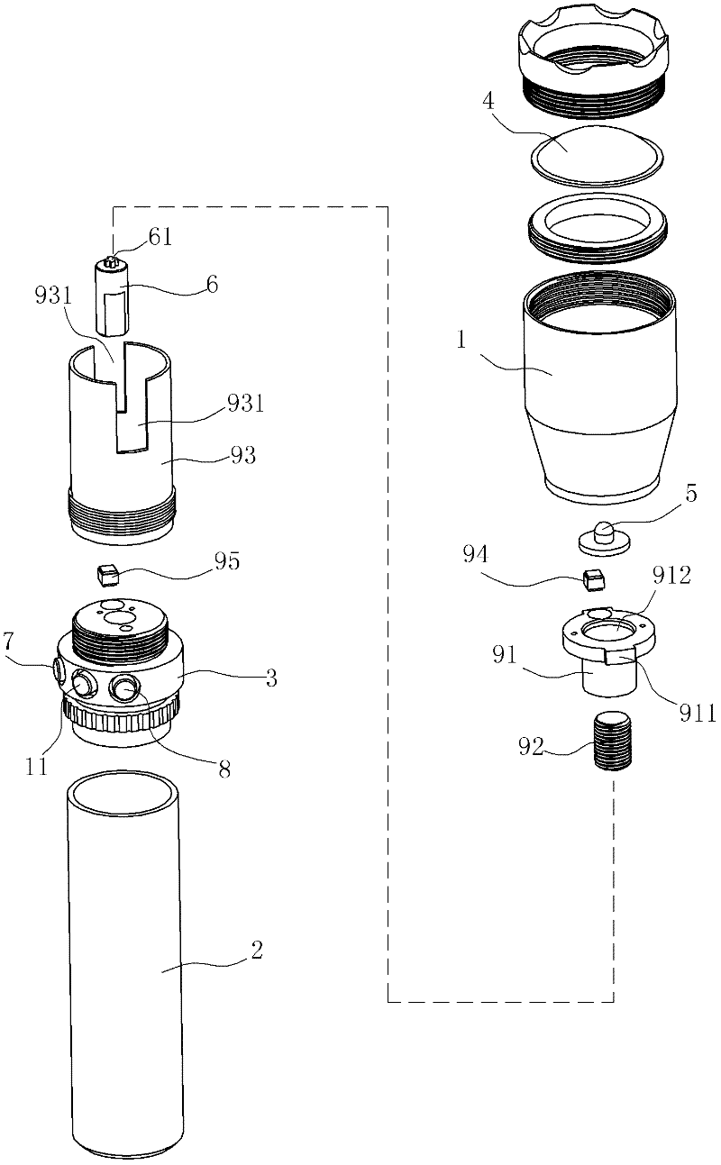
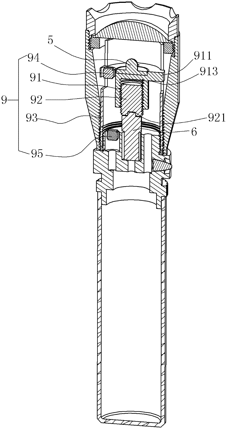
[0032] Such as Figure 1~4 The auto-focus flashlight shown includes a lamp cap 1 and a barrel body 2. A focusing lens 4 is arranged on the head of the lamp cap 1. A luminous body 5 is arranged inside the lamp cap 1. In addition, the interior of the lamp cap 1 also includes a lens for changing the focusing lens and a luminous body. The distance between the automatic distance adjustment mechanism, the automatic distance adjustment mechanism includes

[0033] A power mechanism 6 capable of forward and reverse rotation, which is a motor with a gearbox; a first button switch 7 for starting the forward rotation of the power mechanism; a second button for starting the reverse rotation of the power mechanism A switch 8; a focus adjustment assembly 9 connected to the output shaft of the power mechanism and capable of reciprocating displacement under the drive of the power mechanism, and the illuminant 5 is fixed on the focus adjustment assembly.

[0034] In this embodiment, the power ...

Embodiment 2

[0043] The difference from Embodiment 1 is that the inner wall of the lamp cap is directly provided with orbital grooves 12 distributed along the axial direction of the lamp cap; the focusing assembly 9 includes

[0044]The power mechanism seat 96 arranged inside the lamp cap, the edge of the head of the power mechanism seat 96 is provided with lugs that are clamped in the track groove 12 on the inner wall of the lamp cap, and the head of the power mechanism seat 96 is provided with a ring for fixing the The first groove 961 of the luminous body, the tail of the power mechanism seat is provided with a second groove 962, and the power mechanism 6 is arranged in the second groove 962;

[0045] Screw rod 92, the head of the screw rod 92 is connected with the output shaft of the power mechanism 6;

[0046] The screw rod seat 97 is connected with the lamp head 1 , and the screw rod seat 97 is provided with a thread groove 971 , and the screw rod 92 is screwed in the thread groove 9...


PUM


Abstract

The invention relates to a flashlight capable of focusing automatically. The flashlight comprises a focusing lens fixed on the head of a lamp holder and a luminous body arranged in the lamp holder, and is characterized in that: an automatic distance adjustment mechanism which is used for changing a distance between the focusing lens and the luminous body is arranged in the lamp holder, and comprises a power mechanism capable of performing positive rotation and negative rotation, a first button switch for starting the power mechanism to perform positive rotation, a second button switch for starting the power mechanism to perform negative rotation and a focusing component which is connected with the output shaft of the power mechanism and capable of generating back and forth displacement under the driving of the power mechanism are arranged in the lamp holder, wherein the luminous body is fixed on the focusing component. Compared with the prior art, the flashlight has the advantages that: the automatic distance adjustment mechanism which is used for changing the distance between the focusing lens and the luminous body is arranged in the lamp holder, so that the flashlight can automatically adjust the distance between a light reflection cover and the luminous body under the condition that a lamp holder seat is not required to be manually rotated; and due to the power mechanism used for focusing, an effect is relatively ideal.

Description

technical field [0001] The invention relates to a flashlight, in particular to an automatic focusing flashlight. Background technique [0002] In the prior art, there are quite a lot of flashlight products sold on the market, and the styles and functions are also different. These flashlights can generally change the lighting distance and concentration by adjusting the focal length. The basic structure and focusing principle are: rotate the lamp holder to change the distance between the focusing lens and the illuminant (generally tungsten filament bulb or light-emitting diode) , and then realize the adjustment effect of long-distance lighting (spotlight, high brightness) and short-distance lighting (flood lighting, large area). However, during the focusing process of this type of flashlight, the lamp holder must be manually rotated to change the distance between the focusing lens and the illuminant. Springs are generally arranged inside the lamp holder, which cannot be autom...

Claims


Application Information

Patent Timeline
Patent Type & Authority Applications(China)
IPC IPC(8): F21L4/00F21V14/02
Inventor 徐永伟
Owner 徐永伟
Why Eureka
Try Eureka