Wet sand drying system and dry-mixed mortar mixing station using same

A drying system, wet sand technology, applied in the direction of drying, drying solid materials, lighting and heating equipment, etc., can solve the problems such as the blockage of the sand inlet pipe, and achieve the effect of sufficient material scraping

Active Publication Date: 2014-09-10
SANY HEAVY IND CO LTD (CN)
View PDF5 Cites 0 Cited by
  • Summary
  • Abstract
  • Description
  • Claims
  • Application Information

AI Technical Summary

Problems solved by technology

[0003] The purpose of the present invention is to solve the technical problem of blockage of the lower nozzle of the sand inlet pipe in the wet sand drying system

Method used


Image

  • Wet sand drying system and dry-mixed mortar mixing station using same
  • Wet sand drying system and dry-mixed mortar mixing station using same
  • Wet sand drying system and dry-mixed mortar mixing station using same

Examples


Embodiment 1

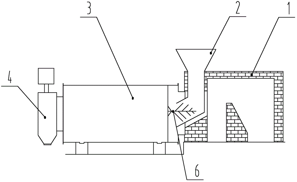
[0025] like figure 2 As shown, the wet sand drying system of the present invention includes a heating device 1, a sand inlet pipe 2, a dryer 3, a discharge port 4 and a scraping device 6, and the heating device 1 is preferably a hot blast stove, or a coal-fired furnace , gas furnace, oil furnace in any one.

[0026] In this embodiment, the dryer 3 can rotate, and the scraper device 6 is installed below the sand inlet pipe 2, and is fixedly connected with the inner wall of the dryer 3, and the wet sand is introduced into the dryer 3 through the sand inlet pipe 2 for supplying The heat device 1 provides enough heat energy for the dryer 3 to dry the sand, and the dried sand is discharged through the discharge port 4, and the scraping device 6 can rotate together with the dryer 3, so that the sand below the sand inlet pipe 2 The accumulated material is cleaned up.

[0027] In other embodiments, the dryer 3 may not rotate, but the scraping device 6 itself can move, and the accum...

Embodiment 2

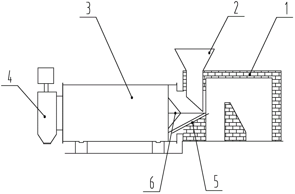
[0029] like image 3 As shown, the difference from Embodiment 1 is that a material guide plate 5 is provided below the discharge port of the sand inlet pipe 2, and the wet sand falls to the material guide plate 5 through the sand inlet pipe 2, and the material guide plate 5 guides the wet sand into the The dryer 3 and the scraping device 6 clean up the accumulated material above the material guide plate 5 to prevent the accumulation of wet sand below the sand inlet pipe 2 and cause blockage.

Embodiment 3

[0031] In this embodiment, the dryer 3 is rotatable, and the drying system may either include a material guide plate 5 or not.

[0032] like Figure 4 As shown, the scraping device 6 includes a support rod 61, a rotating shaft 63, and a scraping blade 64. One end of the supporting rod 61 is connected to the rotating shaft 63, and one end of the scraping blade 64 is arranged on the rotating shaft 63, and is far away from the supporting rod. 61. The symmetric center plane of the scraper blade 64 and the dryer 3 is set with a scraping angle of 45°. In other embodiments, the symmetry center plane of the scraper blade 64 and the dryer 3 can also be set to 0° , 15°, 30°, 60° any angle.

[0033] Preferably, there are three support rods 61, and the three support rods 61 are distributed at a certain angle, preferably 120°. The other end of the scraper blade 64 is connected to one of the support rods, and the other two support rods that are not connected to the scraper blade are connec...


PUM


Abstract

The invention relates to the field of construction machinery, in particular to a wet sand drying system and a dry-mixed mortar mixing station using the same. The purpose of the invention is to solve the technical problem of clogging of the lower nozzle of the sand feeding pipe in the wet sand drying system. Therefore, the present invention provides the following technical solutions: a green sand drying system includes a heating device, a sand feeding pipe, a dryer, a discharge port and a scraping device, and the green sand is introduced into the dryer through the sand feeding pipe , the heating device provides enough heat energy for the dryer to dry sand, the sand after drying is discharged through the discharge port, and the scraping device is installed under the sand feeding pipe, and the Clean up the accumulated material below the sand inlet pipe. Because the scraping device is installed under the sand feeding pipe, the accumulated material under the sand feeding pipe can be cleaned in real time, which solves the technical problem of clogging caused by the accumulation of wet sand under the sand feeding pipe.

Description

technical field [0001] The invention relates to the field of engineering machinery, in particular to a wet sand drying system and a dry-mixed mortar mixing station using the same. Background technique [0002] Most of the raw sand used in the production of dry-mixed mortar mixing plants cannot be directly used in the production of dry-mixed mortar because of its high moisture content. Therefore, the raw sand needs to be dried before use to make its moisture content meet the requirements of dry-mixed mortar production. conditions of. At present, the drying system of the dry-mixed mortar mixing station mostly uses such as figure 1 The main components of the wet sand feeding method shown include: 1'-hot blast stove, 2'-sand feeding pipe, 3'-dryer, 4'-discharging port, 5'-material guide plate. The wet sand falls to the material guide plate 5' below through the sand inlet pipe 2', and the material guide plate 5' guides the wet sand into the dryer 3'. Provide sufficient heat en...

Claims


Application Information

Patent Timeline
Patent Type & Authority Patents(China)
IPC IPC(8): F26B25/04
Inventor 潘焕周亮朱双明
Owner SANY HEAVY IND CO LTD (CN)
Why Eureka
Try Eureka