
Power supply management method and power supply management device for electronic scale

A technology for power management and electronic scales, which is applied in the field of electronics and can solve the problems of too many electronic scales and increased energy consumption of components.

Active Publication Date: 2012-07-11
NEWLAND DIGITAL TECH CO LTD
View PDF4 Cites 1 Cited by
  • Summary
  • Abstract
  • Description
  • Claims
  • Application Information

AI Technical Summary

Problems solved by technology

Such additional functions have led to more and more components of the electronic scale, and the increase in components has brought about the problem of increased energy consumption.

Method used


Image

  • Power supply management method and power supply management device for electronic scale
  • Power supply management method and power supply management device for electronic scale
  • Power supply management method and power supply management device for electronic scale

Examples


no. 1 example

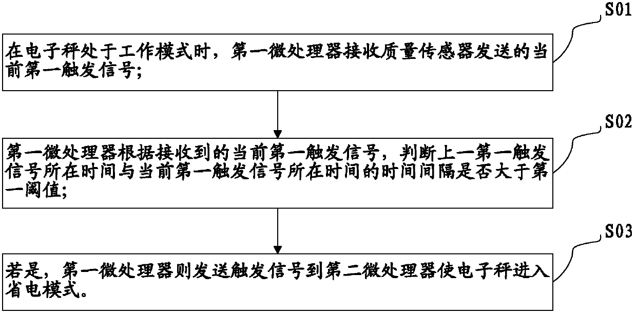
[0042] see figure 2 , in combination with the above-mentioned electronic scale, the first embodiment of the power management method of the electronic scale of the present invention includes the following steps:

[0043] Step S01: When the electronic scale is in the working mode, the first microprocessor receives the current first trigger signal sent by the quality sensor;

[0044] Step S02: The first microprocessor determines whether the time interval between the time of the last first trigger signal and the time of the current first trigger signal is greater than the first threshold according to the received current first trigger signal;

[0045] Step S03: If yes, the first microprocessor sends a trigger signal to the second microprocessor to make the electronic scale enter the power saving mode.

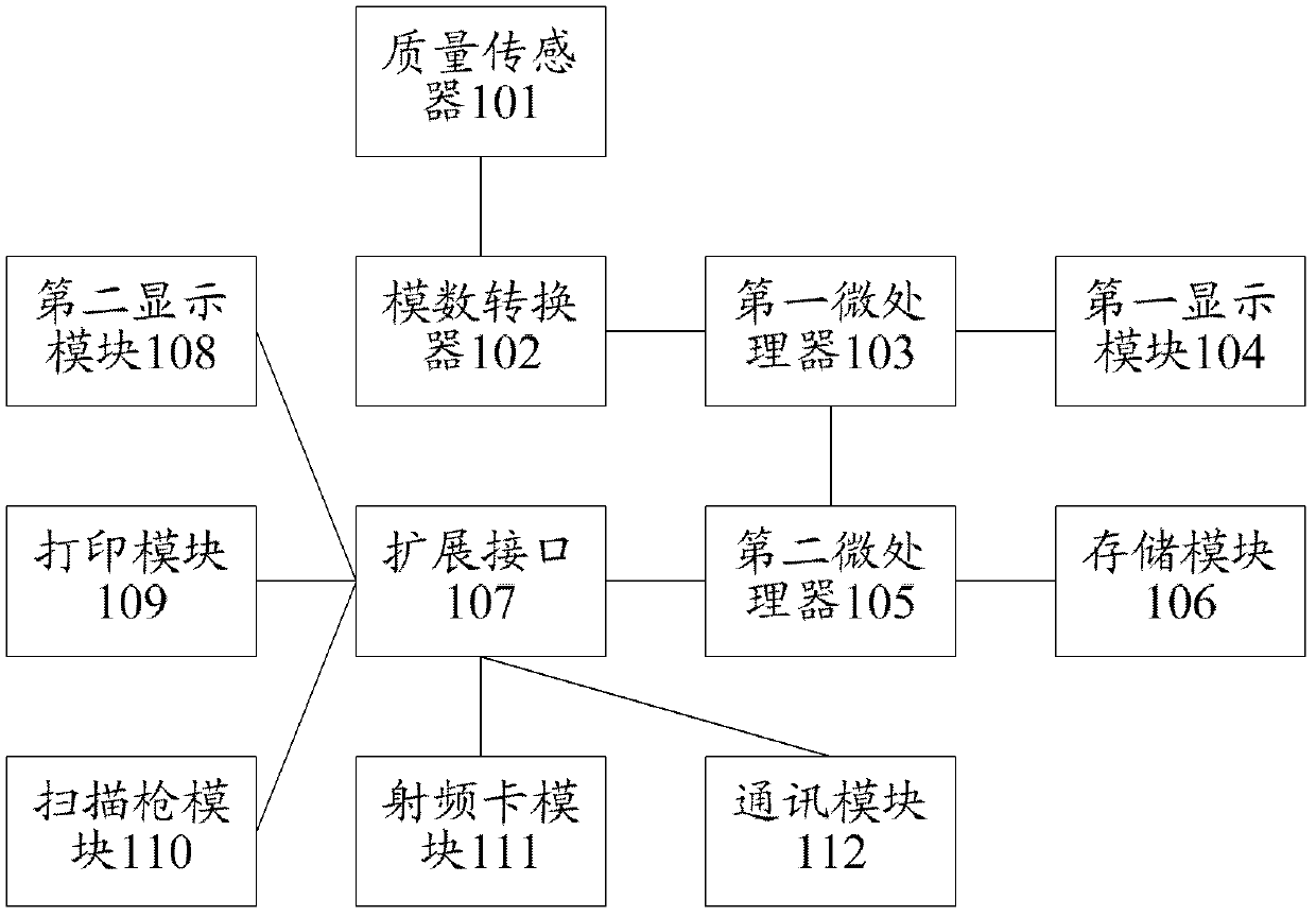
[0046] After entering the power saving mode, only the quality sensor 101, the analog-to-digital converter 102 and the first microprocessor 103 are in the power supply state, whil...

no. 2 example

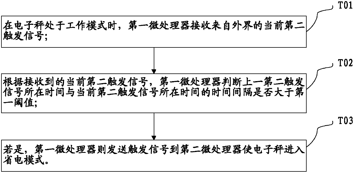
[0051] see image 3 , in combination with the above-mentioned electronic scale, the second embodiment of the power management method of the electronic scale of the present invention includes the following steps:

[0052] Step T01: when the electronic scale is in the working mode, the first microprocessor receives the current second trigger signal from the outside;

[0053] Step T02: According to the current second trigger signal received, the first microprocessor judges whether the time interval between the time of the previous second trigger signal and the time of the current second trigger signal is greater than the first threshold;

[0054] Step T03: If yes, the first microprocessor sends a trigger signal to the second microprocessor to make the electronic scale enter the power saving mode.

[0055] After entering the power saving mode, only the quality sensor 101, the analog-to-digital converter 102 and the first microprocessor 103 are in the power supply state, while the s...


PUM


Abstract

The invention discloses a power supply management method and a power supply management device for an electronic scale. The method comprises receiving a current first trigger signal sent by a quality sensor when the electronic scale is in work mode; judging whether time interval between the current first trigger signal between the current first trigger signal and a first trigger signal on the current first trigger signal is larger than a first threshold; and if being larger, the electronic scale is in power saving mode. The power supply management method and the power supply management device for the electronic scale can sense trigger from the quality sensor or a keyboard to judge whether the electronic scale needs entering power saving mode. If the time interval is larger than the threshold, trigger from the quality sensor or the keyboard is not received. Therefore, the electronic scale is judged to be in power saving mode. In preset time, the electronic scale is not used, an energy consumption module is closed, and the purposes of protecting the environment and saving energy are achieved.

Description

technical field [0001] The invention relates to the field of electronics, in particular to a method and device for power management of electronic scales. Background technique [0002] Electronic scale is a commonly used quality measuring instrument. Compared with traditional mechanical measuring instruments, electronic scale has the advantages of high precision, stable performance, accurate measurement, and convenient use. [0003] With the development of electronic scale technology, digital electronic scales have gradually become the mainstream. A digital electronic scale generally includes a quality sensor, an analog-to-digital conversion module, a microprocessor and a display module. Its working principle is to convert the mass of the measured object into an analog voltage signal through the sensor, then convert the analog voltage signal into a digital signal, send it to the microprocessor for calculation and processing, and send it to the display module after processing...

Claims


Application Information

Patent Timeline
IPC IPC(8): G01G23/00
Inventor 卢景庄华强刘啟瑞
Owner NEWLAND DIGITAL TECH CO LTD
Learn More