radar equipment

A radar equipment, radar wave technology, applied in the direction of reflection/re-radiation of radio waves, utilization of re-radiation, measurement devices, etc., can solve problems such as false detection

Active Publication Date: 2016-07-06
DENSO CORP
View PDF6 Cites 0 Cited by
  • Summary
  • Abstract
  • Description
  • Claims
  • Application Information

AI Technical Summary

Problems solved by technology

[0011] In a radar apparatus that obtains information including a target position by pairing peaks of an upbeat signal Bu and a downbeat signal using the FMCM method, when digital signal processing such as fast Fourier transform (FFT) is performed, occurrences greater than the received The received signal of a target at a distance from the Nyquist frequency of the sampling frequency of the signal may be folded to a position smaller than the Nyquist frequency, and a target located at a long distance may appear at a short distance and may lead to false detections

Method used


Image

  • radar equipment
  • radar equipment
  • radar equipment

Examples


no. 1 example

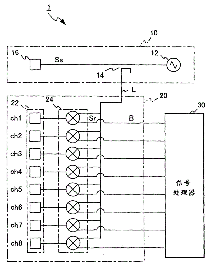
[0075] The radar apparatus 1 according to the first embodiment of the present disclosure is described with reference to the drawings. Such as figure 1 As shown, the radar device 1 includes a transmitter 10, a receiver 20, and a signal processor 30.

[0076] The transmitter 10 generates a transmission signal whose frequency periodically changes with time, and outputs the transmission signal as a radar wave. The transmitter 10 includes an oscillator 12, a distributor 14 and a transmitting antenna 16. The oscillator 12 generates a high-frequency signal in the millimeter wave band whose frequency is modulated to periodically increase or decrease. The distributor 14 divides the power of the output signal of the oscillator 12 into the transmission signal Ss and the local signal L. The transmitting antenna 16 outputs radar waves according to the transmitting signal Ss.

[0077] The frequency of the high-frequency signal generated by the oscillator 12 changes in a triangular wave. For ...

no. 2 example

[0121] Will refer to Figure 7 with Figure 8 The radar device 2 according to the second embodiment of the present disclosure is described.

[0122] Such as Figure 7 As shown, the radar device 2 includes a transmitter 10, a receiver 200, and a signal processor 300. The receiver 200 includes a plurality of receiving antennas 22, a receiving device 24, a receiver switch 26, and a selection signal generator 28.

[0123] The receiving device 24 includes a high-frequency mixer that mixes the received signal Sr from one of the receiving antennas 22 with the local signal L, and generates a beat signal B that is a frequency component of the difference of the signal.

[0124] The receiver switch 26 selects one of the received signals Sr from the receiving antenna 22 based on the selection signal Xr, and supplies the selected received signal to the receiving device 24. The receiver switch 26 may be a high frequency switch, such as a p-intrinsic-n diode (PIN diode), a metal semiconductor fiel...


PUM


Abstract

A radar device including a transmitter, receiver and signal processor. The transmitter outputs radar waves. The receiver includes a plurality of receiving antennas and a plurality of receiving devices. Each of the receiving devices mixes a received signal from a corresponding receiving antenna with a local signal, and outputs a beat signal. The signal processor samples the beat signal while sequentially selecting one of the plurality of receiving apparatuses with a selection period that is less than half the sampling period; compensation, and azimuth information is derived based on the phase difference between the compensated beat signals generated from the received signals of two adjacent receiving antennas. In the case of paired peaks of the beat signal, the signal processor determines the derived azimuth angle information as position information of the target.

Description

Technical field [0001] The invention relates to a radar device for detecting position information of a target. Background technique [0002] Radar equipment is arranged in vehicles and used as a safety device to prevent collisions. As an example of a radar device arranged in a vehicle, a frequency modulated continuous wave radar device (FWCW radar device) is used. The FWCW radar device can detect both the distance of the target and the relative speed of the target. FWCW radar equipment has a simple configuration, suitable for reducing size and cost. [0003] The FM-CW radar device transmits a transmission signal Ss that is frequency-modulated using a triangular wave so that the frequency gradually increases and decreases in a linear manner, and receives the wave reflected by the target as the reception signal Sr. [0004] The received signal Sr delay time Td, which is the time it takes for the transmitted and received waves to travel from the radar device to the target and return,...

Claims


Application Information

Patent Timeline
Patent Type & Authority Patents(China)
IPC IPC(8): G01S13/42G01S13/58G01S13/931
CPCG01S3/465G01S7/354G01S13/343G01S13/42G01S13/58G01S13/931G01S13/345
Inventor 水谷玲义夏目一马阿部好浩
Owner DENSO CORP
Why Eureka
Try Eureka