Rotation angle detecting device and rotary drive unit by use thereof

A technology of rotation angle detection and rotation angle, which is applied in the field of rotation angle detection device and rotation drive unit, and can solve problems such as wrong detection of rotation angle

Active Publication Date: 2014-05-07
DENSO CORP
View PDF7 Cites 5 Cited by
  • Summary
  • Abstract
  • Description
  • Claims
  • Application Information

AI Technical Summary

Problems solved by technology

As a result, false detection of the rotation angle can result

Method used


Image

  • Rotation angle detecting device and rotary drive unit by use thereof
  • Rotation angle detecting device and rotary drive unit by use thereof
  • Rotation angle detecting device and rotary drive unit by use thereof

Examples


no. 1 example )

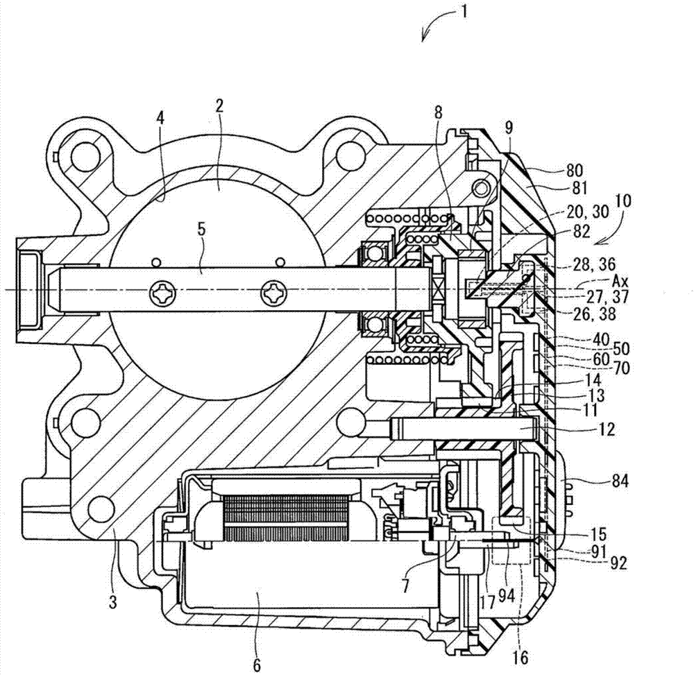
[0019] The rotation angle detection device in the first embodiment and the rotation driving unit to which it is applied are shown in figure 1 middle. The rotation drive unit 1 is used to rotate, for example, a throttle valve 2 provided in an intake system (intake system) of a vehicle. The rotary drive unit 1 includes a housing 3 , a valve shaft 5 , a motor 6 and a rotation angle detection device 10 .

[0020] The housing 3 is formed of metal such as aluminum, and includes therein a passage 4 having a substantially cylindrical shape. The channel 4 constitutes an intake channel for guiding intake air into the internal combustion engine. The valve shaft 5 is formed in a rod shape and is arranged rotatably relative to the housing 3 so that the shaft 5 is substantially perpendicular to the channel axis of the channel 4 .

[0021] The throttle valve 2 is formed in a substantially circular plate shape, and it is attached to a valve shaft 5 by, for example, a screw member. Theref...

no. 2 example )

[0065] The rotation drive unit and the rotation angle detection device in the second embodiment are partially shown in Figure 5 and Figure 6 middle. The second embodiment differs from the first embodiment in the shape of the ground line of the rotation angle detection device.

[0066]In the second embodiment, the ground line 50 includes a linear connection portion 55 instead of the bypass wiring portion 54 of the first embodiment. The linear connection portion 55 is linearly formed to connect the first ground portion 51 and the second ground portion 52 together. Therefore, the first ground portion 51 and the second ground portion 52 are linearly connected. The configuration of the second embodiment is similar to that of the first embodiment except for the above-mentioned points.

[0067] As described above, in the current embodiment, the first ground portion 51 and the second ground portion 52 are connected by the linear connection portion 55 . Therefore, if heat is appl...

no. 3 example )

[0069] The rotation drive unit and the rotation angle detection device in the third embodiment are partially shown in Figure 7 middle. The third embodiment differs from the first embodiment in the arrangement of the first IC package and the second IC package, the shape and arrangement of wiring, and the like.

[0070] In the third embodiment, the first IC package 20 and the second IC package 30 are insert molded by the main forming body 82, wherein one surface 251 of the sealing body 25 in the first IC package 20 and the sealing body in the second IC package 30 The other surface 352 of the body 35 is in contact. Therefore, the distance from the rotation axis Ax to the first magnetic detection element 21 and the second magnetic detection element 31 is long compared with the first and second embodiments. However, both the first magnetic detection element 21 and the second magnetic detection element 31 may be arranged at positions relatively close to the rotation axis Ax.

[...


PUM


Abstract

The invention discloses a rotation angle detecting device and a rotary drive unit by use thereof. In the rotation angle detecting device, a signal from a first magnetism detecting element is outputted to a signal output part of a first IC package. A first signal output terminal outputs the signal from the first magnetism detecting element to outside. A signal from a second magnetism detecting element is outputted to a signal output part of a second IC package. A second signal output terminal outputs the signal from the second magnetism detecting element to outside. At least one of a power supply terminal and a ground terminal is located between the first and second signal output terminals. A rotary drive unit includes the device, a motor that rotates a detection object, and a motor power source wire. The ground terminal and a motor power source terminal are adjacent to each other.

Description

technical field [0001] The present invention relates to a rotation angle detection device for detecting a rotation angle of a detection object and a rotation drive unit using the same. Background technique [0002] Conventionally, there is known a rotation angle detection device having two integrated circuit (IC) packages each including a magnetic detection element. In, for example, JP-A-2004-004114, a rotation angle detection device is described in which two IC packages are arranged side by side along the board surface direction (see JP-A-2004-004114 Figure 6 ). In this rotation angle detection device, two magnetic detection elements are arranged at positions away from the rotation axis of the detection object. Therefore, by providing the stator with a magnetic collecting effect, deterioration of sensor characteristics is limited. [0003] In the case of the above-described rotation angle detection device, if the stator is removed for cost reduction, the sensor character...

Claims


Application Information

Patent Timeline
IPC IPC(8): G01B7/30H02K11/00
CPCG01D5/12G01D3/028G01D5/145G01B7/30G01D5/20
Inventor 水沼赳人泷口智之水谷彰利河野祯之
Owner DENSO CORP
Why Eureka
Try Eureka