Optical unit and tool for adhering optical elements

A technology of optical components and optical units, which is applied in the direction of optical components, optics, installation, etc., can solve the problems of reducing the performance of optical components, shifting and sliding of windows and prisms, etc., so as to achieve the same relative position, avoid air bubbles, and improve optical quality. The effect of precision

Inactive Publication Date: 2012-07-11
BEIJING GK LASER TECH
View PDF7 Cites 0 Cited by
  • Summary
  • Abstract
  • Description
  • Claims
  • Application Information

AI Technical Summary

Problems solved by technology

[0003] When using UV glue to bond the window and prism, since the UV lamp has a built-in good fan cooling system with filtering function to ensure high reliability of the system, after coating the surface of the window with UV glue, irradiate it with UV light to cure it During the process, there is wind blowing out from the ultraviolet lamp, which easily causes the relative displacement and sliding of the window and the prism, which changes the position of the optical unit assembled from the above optical elements and reduces the performance of the optical elements.

Method used


Image

  • Optical unit and tool for adhering optical elements
  • Optical unit and tool for adhering optical elements
  • Optical unit and tool for adhering optical elements

Examples


Embodiment 1

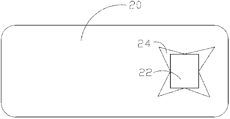
[0021] Such as figure 1 As shown, the embodiment of the present invention provides a tool for bonding optical elements, which includes a tool body 20 and a window portion 22 , and the window portion 22 runs through the tool body 20 . The window portion 22 includes four openings 24 , and the four openings 24 are symmetrically arranged at edge positions of the window portion 22 . The shape and size of the window portion 22 are set in accordance with the external optical elements. In Embodiment 1 of the present invention, the window part 22 is arranged in a quadrangular shape according to the shape of the external optical element, and four openings 24 are symmetrically arranged at the four corners of the window part 22 . Each opening 24 is a triangle whose bottom is disposed in the window 22 . The frock body 20 is used for bonding with an external optical element, the window portion 22 is used for positioning the bonding position of the external optical element for bonding, and...

Embodiment 2

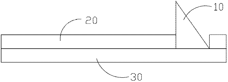
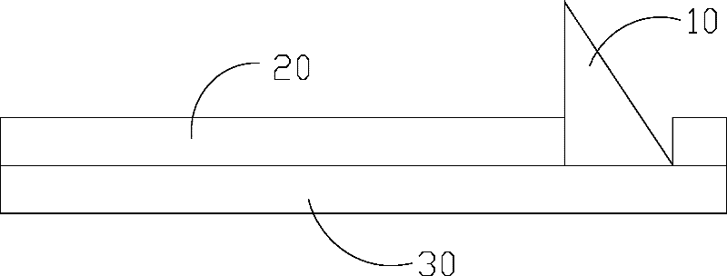
[0024] Such as figure 2 As shown, an optical unit provided by an embodiment of the present invention includes a prism 10 , a tooling 20 and a window 30 , and the tooling 20 is arranged between the prism 10 and the window 30 . The prism 10 is disposed on the window 30 through the tooling.

[0025] see again figure 1 , the frock includes a frock body 20 and a window portion 22 , and the window portion 22 runs through the frock body 20 . The window portion 22 includes four openings 24 , and the four openings 24 are symmetrically arranged at edge positions of the window portion 22 . The shape and size of the window portion 22 are set in accordance with the external optical elements. In Embodiment 2 of the present invention, the window portion 22 is configured as a quadrangle according to the shape of the prism, and four openings 24 are symmetrically disposed at the four corners of the window portion 22 . Each opening 24 is a triangle whose bottom is disposed in the window 22 ...


PUM


Abstract

The invention relates to an optical unit and a tool for adhering optical elements. The optical unit comprises a prism, a diaphragm and the tool, wherein the tool is arranged between the prism and the diaphragm and comprises a tool main body and at least one window part; and the window part penetrates through the tool main body and comprises four opening parts which are symmetrically arranged at the edge of the window part. By the invention, the position of the optical unit is relatively stabilized, and the using performance of the optical unit is improved.

Description

technical field [0001] The invention relates to an optical unit and a tool for bonding optical elements. Background technique [0002] Ultraviolet glue (UV glue, UV is the abbreviation of Ultraviolet Rays in English, that is, ultraviolet light.) Also known as shadowless glue and photosensitive glue, it refers to a type of adhesive that must be cured by ultraviolet light. It will almost never cure under normal conditions. Since this type of adhesive is almost all composed of acrylate prepolymers (also known as oligomers), active monomers and ultraviolet photoinitiators, the photoinitiators cannot be made to act without ultraviolet radiation, and the prepolymers cannot be further developed. Polymerization forms macromolecules (solids) and solidifies. It is also for this reason that UV glue is generally only used for surface coating (UV varnish, UV ink, UV coating, etc.) or component binding (fixation), or transparent and transparent or transparent and non-transparent The bo...

Claims


Application Information

Patent Timeline
Patent Type & Authority Applications(China)
IPC IPC(8): G02B7/18G02B7/00
Inventor 樊仲维唐熊忻邱基斯
Owner BEIJING GK LASER TECH
Why Eureka
Try Eureka