Three-dimensional imaging equipment

An imaging device, a three-dimensional technology, applied in stereo systems, image communication, optics, etc., can solve the problems of long distance, obstructing light, image distortion, etc., and achieve the effect of wide application prospects, low cost, and ingenious design

Inactive Publication Date: 2012-07-11
刘武强
View PDF7 Cites 6 Cited by
  • Summary
  • Abstract
  • Description
  • Claims
  • Application Information

AI Technical Summary

Problems solved by technology

[0004] In this patent, a problem that arises in such an arrangement of the displays is: if the sizes of the displays are the same, and each two-dimensional layer is made according to the size of a real three-dimensional scene during production, and the image of each two-dimensional layer The distance from the human eye is farther than the distance between the real two-dimensional layers and the human eye, so because of the viewing distance, the image of each two-dimensional layer seen by the human eye is larger than the real two-dimensional layer seen by the human eye If it is smaller, the image will be distorted. In order to eliminate the size distortion caused by the distance between the two groups of plane display units, the size of the two-dimensional plane display units is different. The two-dimensional plane display unit is the imaging window, and the area sizes of the two-dimensional plane display units from far to near the imaging window are respectively N of the imaging window size. 2 Times... 16 times, 9 times and 4 times
[0008]

Method used


Image

  • Three-dimensional imaging equipment
  • Three-dimensional imaging equipment
  • Three-dimensional imaging equipment

Examples


Example Embodiment

[0032] Example 1

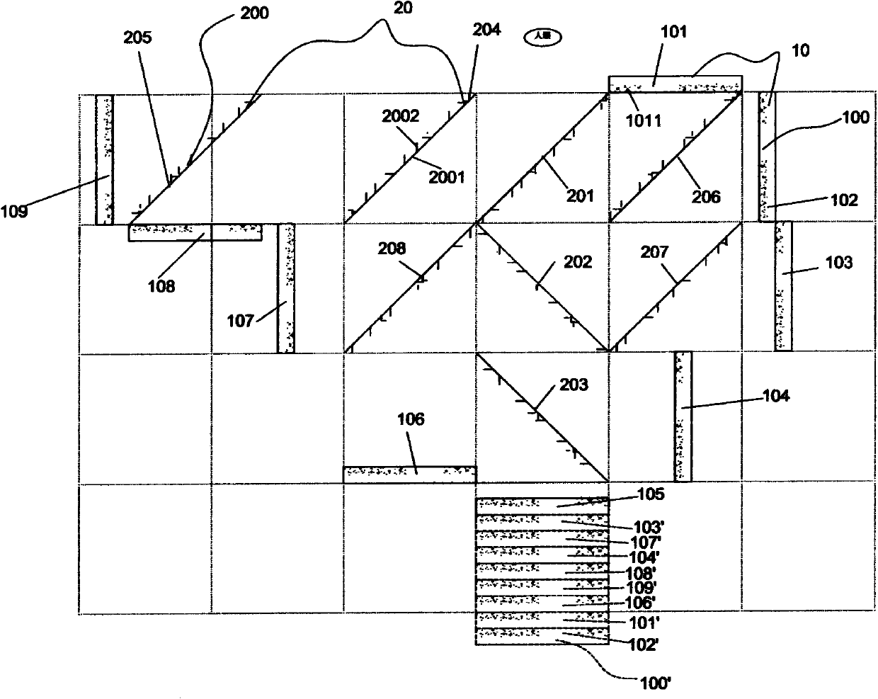
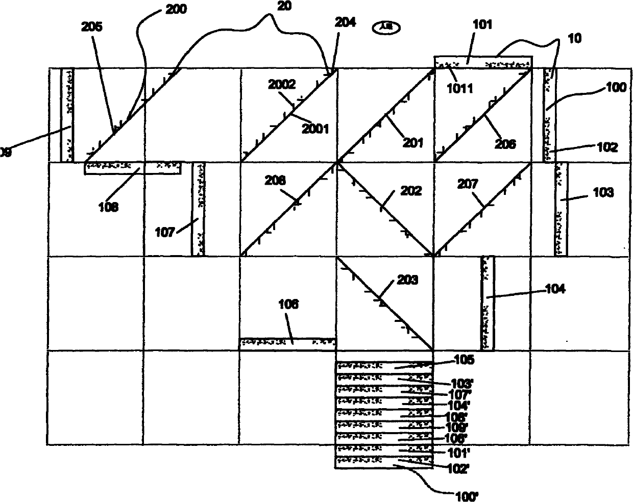
[0033] like figure 1 As shown, the present embodiment relates to a three-dimensional imaging device, and the three-dimensional imaging device is used for displaying nine two-dimensional layers divided into three-dimensional scenes to form nine two-dimensional pictures, and making each two-dimensional picture The image of the original three-dimensional scene is assembled into the image of the original three-dimensional scene; the device includes a display device 10 and a polarizing device 20, and the polarizing device 20 includes eight square plate semi-reflective and semi-transparent optical devices 200 of the same size, and the semi-reflective and semi-transparent optical device 200 includes a reflective surface 2001 for reflecting light and a transmissive surface 2002 for transmitting light. The reflective surface 2001 and the transmissive surface 2002 are located on opposite sides of the transflective optical device 200 (each transflective optical device ...

Example Embodiment

[0037] Example 2

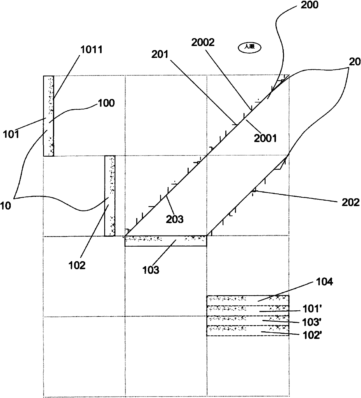
[0038] like figure 2 As shown, the present embodiment relates to a three-dimensional imaging device, which is used for displaying four two-dimensional layers divided into three-dimensional scenes to form four two-dimensional pictures, and making each two-dimensional pictures The image of the original three-dimensional scene is assembled into the image of the original three-dimensional scene; the device includes a display device 10 and a polarizing device 20, and the polarizing device 20 includes three square plate semi-reflective and semi-transparent optical devices 200 of the same size, and the semi-reflective and semi-transparent optical device 200 includes a reflective surface 2001 for reflecting light and a transmissive surface 2002 for transmitting light. The reflective surface 2001 and the transmissive surface 2002 are located on opposite sides of the transflective optical device 200 (each transflective optical device in the figure One side with burr...


PUM


Abstract

The invention provides three-dimensional imaging equipment, which is used for respectively displaying a plurality of two-dimensional layers formed by cutting of a three-dimensional scene to form a plurality of two-dimensional pictures, and enabling images of the two-dimensional pictures to be combined into images of the three-dimensional scene. The equipment comprises a display device and a light polarizing device. The equipment is characterized in that: the light polarizing device comprises a plurality of square flat semi-reflective semi-transparent optical devices with the same sizes; each semi-reflective semi-transparent optical device comprises a reflection surface for reflecting light rays and a transmission face for transmitting light rays; the reflection face and the transmission face are located on two opposite faces of each semi-reflective semi-transparent optical device; the semi-reflective semi-transparent optical devices are mutually parallel or vertical; the display device comprises a plurality of square flat displays; all the displays and the semi-reflective semi-transparent optical devices are all vertical to the same plane; each display forms a 45-degree angle with the reflection face or the transmission face of each semi-reflective semi-transparent optical device; and the centers of the images formed by the displays in the first semi-reflective semi-transparent optical device are located on the same straight line.

Description

【Technical field】 [0001] The invention belongs to the technical field of three-dimensional imaging, and relates to a three-dimensional imaging device. 【Background technique】 [0002] The most fundamental difference between 3D display and 2D display is that various methods should be used to bring visual depth perception to the viewer, so that people can naturally or unnaturally obtain the third-dimensional information in the picture. For 3D stereoscopic imaging technology, it is very important to restore the real physical depth of field in 3D stereoscopic space, and it is also the most critical factor for human eyes to perceive 3D stereoscopic images. [0003] The inventor previously introduced a three-dimensional imaging method in the Chinese invention patent with the patent application number 200910109909.X (application date: February 1, 2010), which is to longitudinally cut the three-dimensional scene according to the depth of the physical scene. into a number of two-dime...

Claims


Application Information

Patent Timeline
IPC IPC(8): G02B27/26H04N13/00G02B30/25
CPCG02B27/283G02B27/2242G02B27/2235G02B30/35G02B30/36
Inventor 刘武强
Owner 刘武强
Why Eureka
Try Eureka