Cooling device for vehicle

A technology for cooling devices and vehicles, applied in engine cooling, coolant flow control, failure prevention, etc., can solve problems such as control obstacles

Inactive Publication Date: 2012-07-11
TOYOTA JIDOSHA KK
View PDF6 Cites 23 Cited by
  • Summary
  • Abstract
  • Description
  • Claims
  • Application Information

AI Technical Summary

Problems solved by technology

In this way, in the conventional vehicle cooling device, the cooling water in the engine 50 may be mixed with low-temperature cooling water in a state where the temperature has been sufficiently raised, which may hinder the control based on the cooling water temperature.

Method used


Image

  • Cooling device for vehicle
  • Cooling device for vehicle
  • Cooling device for vehicle

Examples


no. 1 example 1

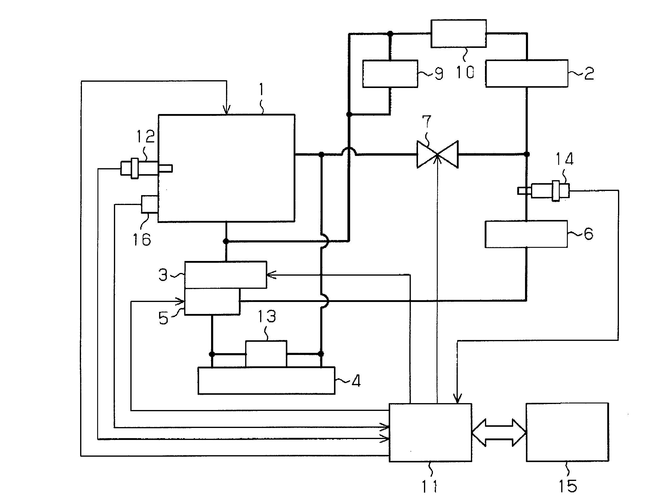
[0061] Below, according to Figure 1 to Figure 8 A first embodiment in which the present invention is embodied in a vehicle cooling device will be described.

[0062] figure 1 The structure of the cooling water circuit of the vehicle cooling device of this embodiment is shown. This cooling device includes a first cooling water circuit that circulates cooling water through the inside of the engine 1 , and a second cooling water circuit that circulates cooling water through the exhaust heat recovery device 2 without passing through the inside of the engine 1 . The cooling water in these cooling water circuits can be circulated individually by the same water pump 3 . The water pump 3 is an electric pump, and can change the flow rate of the cooling water to be discharged based on an external command. In addition, the exhaust heat recovery device 2 functions as a heat exchanger for exchanging heat between the exhaust gas of the engine 1 and the cooling water of the second cooli...

no. 2 approach

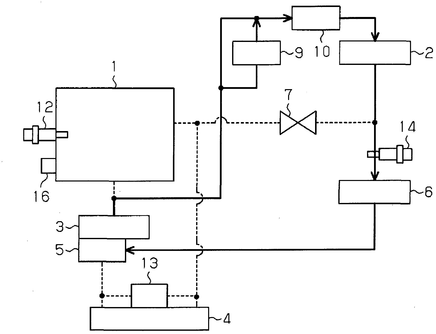
[0097] Next, based on Figure 9 to Figure 16 A second embodiment of the present invention will be described.

[0098] In this embodiment, when the failure of the valve to open occurs in the valve 7, in order to suppress the overheating of the engine 1, the circulation of the cooling water in the bypass path of the first cooling water circuit is carried out instead of forcing The thermostat 5 is opened to circulate the cooling water through the main path of the first cooling water circuit.

[0099] Specifically, in the vehicle cooling device of this embodiment, the following structure is adopted: even if the valve 7 fails to open, by making the discharge flow rate of the water pump 3 more than the normal use range, the cooling water is cooled in the first cooling stage. Circulation in a bypass path in a water circuit. As such a configuration, it is conceivable to specifically make the valve 7 into Figure 9 The composition of the representation. The structure of the valve 7...

no. 3 approach

[0108] Next, based on Figure 17 A third embodiment of the present invention will be described. This embodiment is an example for coping with a failure such as disconnection of one of the water temperature sensors 12 and 14 in the first embodiment.

[0109] When one of the water temperature sensors 12 and 14 fails, the temperature of the cooling water detected by the failed water temperature sensor becomes a value different from the actual value. various controls. For example, when the water temperature sensor 12 fails, various controls of the engine 1 cannot be properly performed based on the cooling water temperature thw1, and when the water temperature sensor 14 fails, the air in the heater core 6 cannot be appropriately controlled based on the cooling water temperature thw2. Heating control and control of blowing the heated air into the vehicle interior.

[0110] Therefore, in the vehicle cooling device of the present embodiment, when one of the water temperature sensor...


PUM


Abstract

A cooling device for vehicle. When the temperature of cooling water within an engine (1) becomes equal to or higher than a partially warmed-up determination value which is set to a temperature lower than a determination value for the completion of warm-up of the engine (1), an engine cooling control unit (11) opens a valve (7) to mix together cooling water in both cooling water circuits. Even if mixing of the cooling water having different temperatures increases and decreases the temperature of the cooling water within the engine (1), the increase and decrease in the temperature occur in a region of temperatures lower than the determination value for the completion of warm-up of the engine (1), and this avoids a situation in which control before the completion of warm-up and control after the completion of the warm-up are performed repeatedly and alternately. Accordingly, in mixing of cooling water circulating in a first cooling water circuit and cooling water circulating in a second cooling water circuit, control on the basis of the temperature of the cooling water within the engine (1) can be performed without any problem.

Description

technical field [0001] The present invention relates to vehicle cooling devices. Background technique [0002] Conventionally, a vehicle cooling device has been proposed that includes a first cooling water circuit that circulates cooling water through an engine and a second cooling water circuit that circulates cooling water without passing through an engine, and each of these circuits can circulate cooling water independently. In such a cooling device, the first cooling water circuit is used for cooling the engine, and the second cooling water circuit is used for recovering exhaust heat from the engine and heating the vehicle interior as disclosed in Patent Document 1. [0003] Figure 19 The structure of the cooling device of the said patent document 1 is shown. The cooling water circulated in the first cooling water circuit in this device is discharged from the first water pump 52 and then passes through the inside of the engine 50. After dissipating heat in the radiator...

Claims


Application Information

Patent Timeline
Patent Type & Authority Applications(China)
IPC IPC(8): F01P11/16F01P7/16
CPCF01P7/165F01P2031/32F01P11/14F01P11/16F01P2060/08F01P2060/16
Inventor 木野村茂树齐藤立树
Owner TOYOTA JIDOSHA KK
Why Eureka
Try Eureka