Eureka AIR delivers breakthrough ideas for toughest innovation challenges, trusted by R&D personnel around the world.

Electric machine, hydraulics unit

A technology of rotor shaft and centrifugal disc, which is applied in the field of hydraulic units of motor vehicles, can solve problems such as damage functions, and achieve the effect of long service life

Inactive Publication Date: 2012-07-11
ROBERT BOSCH GMBH
View PDF6 Cites 2 Cited by
  • Summary
  • Abstract
  • Description
  • Claims
  • Application Information

AI Technical Summary

Problems solved by technology

The disadvantage of the motor described is that liquid can flow through the rolling element bearings that support or support the rotor shaft or can be squeezed / transported due to capillary effects
For electric motors this can lead to lubricant flushed out of the bearings reaching the commutator and impairing its function

Method used


Image

  • Electric machine, hydraulics unit
  • Electric machine, hydraulics unit
  • Electric machine, hydraulics unit

Examples


Embodiment Construction

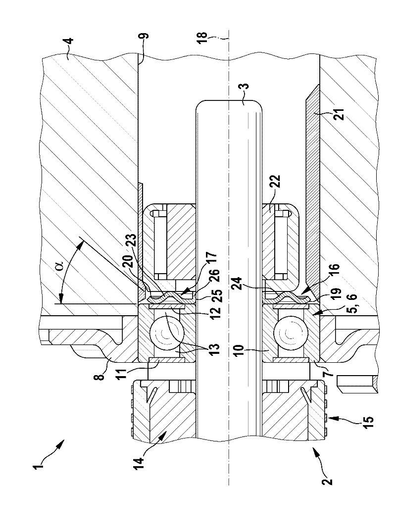
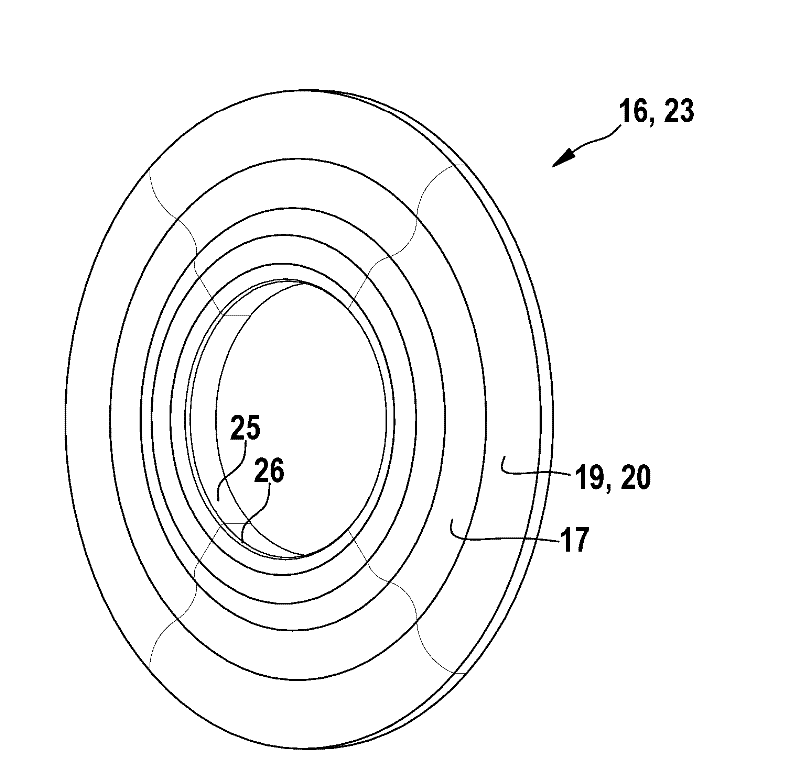
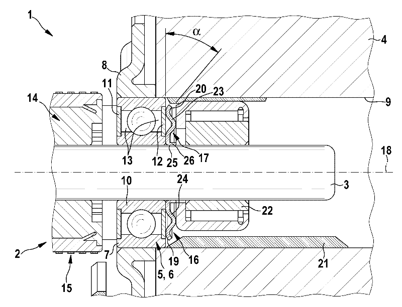
[0017] figure 1 A simplified sectional illustration of a section of hydraulic unit 1 is shown. The hydraulic unit 1 includes an electric motor 2 whose rotor shaft 3 is mounted in a housing 4 . The housing 4 is therefore a component not only of the hydraulic unit 1 but also of the electric machine 2 . A rolling element bearing 5 is provided for supporting the rotor shaft 3 , which is presently designed as a ball bearing 6 . The rolling element bearing 5 is substantially held radially on its outer ring 7 by a bearing cover 8 and protrudes partially into a receptacle 9 of the housing 4 . The rolling element bearing 5 also has an inner ring 10 which is arranged in a rotationally fixed manner on the rotor shaft 3 . The rolling bodies in the form of balls are guided between the outer ring 7 and the inner ring 10 into corresponding grooves. The rolling element bearing 5 is sealed on its axial end faces by means of sealing rings 11 , 12 , wherein the sealing rings 11 , 12 are fast...


PUM


Abstract

The invention relates to an electric machine (2), comprising at least one rotor shaft (3) that is rotatably mounted in a housing (4) by means of at least one rolling body bearing (5), wherein at least one commutator (14) is arranged in a rotationally fixed manner on the rotor shaft (3). To this end, a centrifugal disc (16) is arranged in a rotationally fixed manner on the rotor shaft (3) on the side of the rolling body bearing (5) opposite of the commutator (14). The invention further relates to a hydraulics unit (1), in particular for a motor vehicle, comprising a housing (4) and an electric machine (2).

Description

technical field [0001] The invention relates to an electric machine with at least one rotor shaft, which is rotatably mounted in a housing by means of at least one rolling element bearing, wherein at least one commutator is arranged on the rotor shaft in a rotationally fixed manner. . [0002] Furthermore, the invention relates to a hydraulic unit, in particular for a motor vehicle, which has a housing and an electric motor. Background technique [0003] Electric motors and hydraulic units of the type mentioned here are known from the prior art. The electric motor has a mechanically operated commutator and is intended to be used in applications where liquid can reach the housing of the electric motor. A disadvantage of this electric machine is that the liquid can flow through the rolling element bearing which supports or mounts the rotor shaft or can be squeezed / transported by capillary effect. Rolling element bearings are generally provided with lubricants in order to mi...

Claims


Application Information

Patent Timeline
Patent Type & Authority Applications(China)
IPC IPC(8): H02K5/124
CPCH02K13/006H02K5/124H02K5/10F16C33/7886F16C33/7816
Inventor A-B.伊塞尔
Owner ROBERT BOSCH GMBH
Why Eureka
Eureka Blog
Learn More