Modified structure of brake device of spinning bike

A braking device and spinning technology, applied to sports accessories, bicycle accessories, bicycle brakes, etc., can solve the problems of unsatisfactory braking effect and effort, and achieve the effect of convenient braking and easy use

Inactive Publication Date: 2012-07-18
昆山亚新鸿运动器材有限公司
View PDF6 Cites 2 Cited by
  • Summary
  • Abstract
  • Description
  • Claims
  • Application Information

AI Technical Summary

Problems solved by technology

[0002] The current spinning brake device used by people often needs a lot of force to brake in a short ti

Method used


Image

  • Modified structure of brake device of spinning bike
  • Modified structure of brake device of spinning bike
  • Modified structure of brake device of spinning bike

Examples


Embodiment Construction

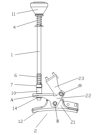
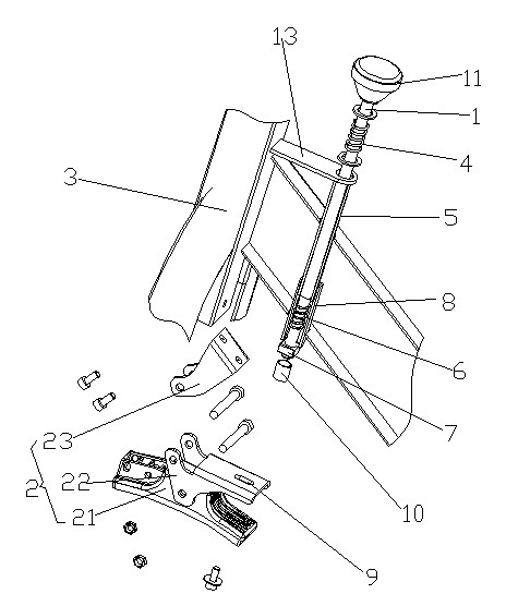
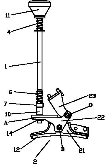
[0024] An improved structure of a spinning bicycle brake device, which includes a brake lever 1 and a brake base 2 arranged on a vehicle frame 3, one end of the brake base is facing the flywheel of the spinning bike, and the brake base is composed of a brake adjustment seat 21, a brake connecting plate 22 and Brake fixing frame 23 is formed, and one end face of brake adjusting seat faces flywheel, and brake fixing frame is connected with vehicle frame, and one end of brake fixing frame and brake connecting plate is pivotally connected to form a pivot point O; one end of brake lever is positioned and connected along its axial direction ( That is, stop along the brake lever axial direction) to form a power action point A at the other end of the brake connecting plate; any place on the brake connecting plate between the pivot point O and the power action point A is the same as the brake adjustment seat away from the flywheel. The side pivots form resistance pivot point B. In this...


PUM


Abstract

The invention discloses a modified structure of a brake device of a spinning bike. The modified structure comprises a brake rod and a brake base. The brake rod and the brake base are disposed on a frame, an end surface of the brake base is opposite to a flywheel of the spinning bike, the brake base consists of a brake adjusting seat, a brake connecting plate and a brake fixing rack, an end surface of the brake adjusting seat is opposite to the flywheel, the brake fixing rack is fixedly connected with the frame, and the brake fixing rack and one end of the brake connecting plate are pivoted to form a pivoting fulcrum; one end of the brake rod is axially connected to the other end of the brake connecting plate in a positioning manner so as to form a power action point; and an optional position between the pivoting fulcrum and the power action point on the brake connecting plate is pivoted with one side, which is far away from the flywheel, of the brake adjusting wheel to form a resistance pivoting point. The brake device not only is simple in structure, but also is fine in labor-saving and braking effects.

Description

technical field [0001] The invention relates to an improved structure of a spinning brake device. Background technique [0002] Currently used spinning brakes, people often need a lot of power to brake in a short time when they are in urgent need of braking, which is not only laborious, but also the braking effect is not ideal. Contents of the invention [0003] In order to overcome the above-mentioned defects, the present invention provides an improved structure of a spinning bicycle braking device. The braking device not only has a simple structure, but also saves labor and has a good braking effect. [0004] The technical solution adopted by the present invention in order to solve the technical problem is: an improved structure of a spinning bicycle brake device, which includes a brake lever and a brake base arranged on the vehicle frame, one end of the brake base faces the flywheel of the spinning bicycle, The brake base is composed of a brake adjusting seat, a brake ...

Claims


Application Information

Patent Timeline
IPC IPC(8): A63B23/04A63B22/08B62L3/02
Inventor 吴东勇
Owner 昆山亚新鸿运动器材有限公司
Why Eureka
Try Eureka