Stepped Torque Braking Device

Active Publication Date: 2020-09-24
WARNER ELECTRIC EURO
View PDF0 Cites 0 Cited by
  • Summary
  • Abstract
  • Description
  • Claims
  • Application Information

AI Technical Summary

Benefits of technology

This patent describes a braking device that uses magnetic armatures and friction discs to provide a larger braking force while keeping the space requirement for the device the same. The device also ensures that the thrust forces are perfectly aligned and increases braking efficiency. Another advantage of the invention is that the braking device can be easily assembled and installed on site. A technical effect of the invention is the increased braking force without sacrificing space requirement and ensuring optimal alignment of the thrust forces.

Problems solved by technology

Such a device allows a braking force that is stepped but limited due to a significant space requirement, and it requires current means of control that are complex and precise.
This braking device cannot tolerate dimensional variations of the components.
The concentric arrangement of the armatures and windings results in considerably increasing the total space required for the braking device, making it difficult to accommodate it in some motor housings.
This ensures that the friction discs are not in contact with the intermediate flange, in the absence of braking, which could generate premature wear of the friction discs, hinder the operation of the motor that drives the shaft or create problems such as undesirable noises or increased temperature of the braking device.

Method used


Image

  • Stepped Torque Braking Device
  • Stepped Torque Braking Device
  • Stepped Torque Braking Device

Examples


Embodiment Construction

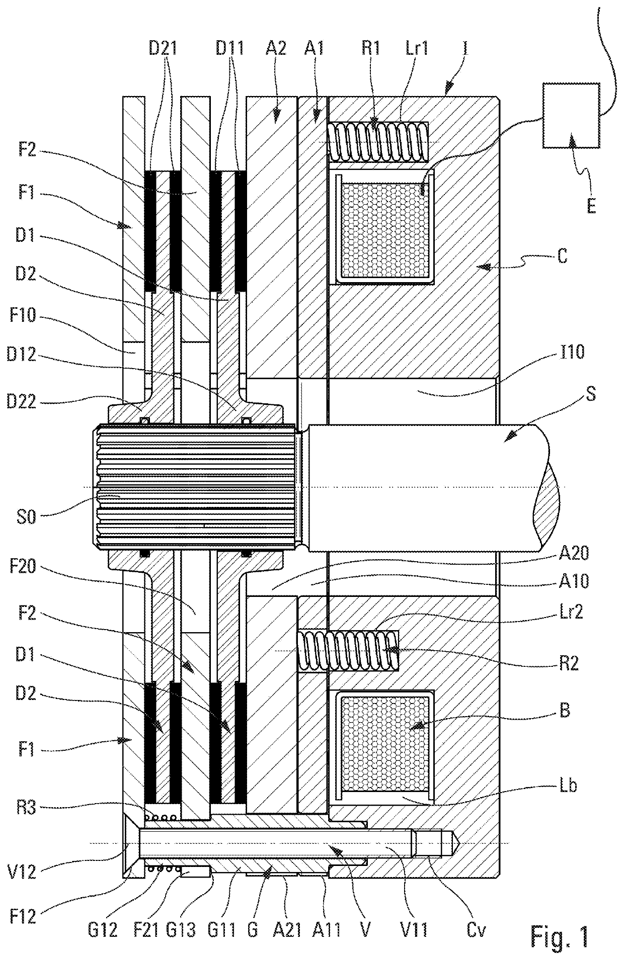
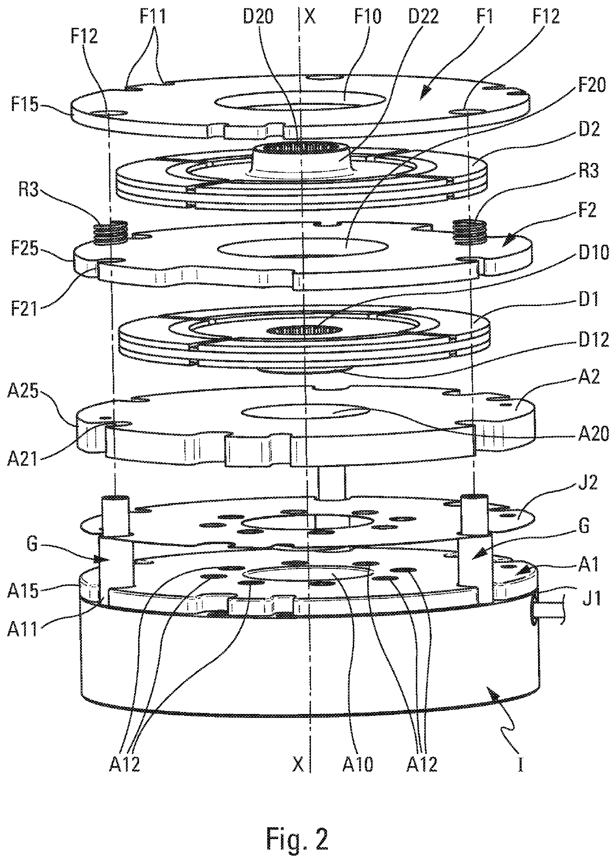
[0033]Reference is made first to FIGS. 1 and 2 for a detailed explanation of the structure and operation of the electromagnetic braking device for a rotary shaft of the invention.

[0034]The electromagnetic braking device of the invention, in the first embodiment of FIGS. 1 and 2, is mounted on a single rotary shaft S, which comprises a splined shaft end S0. This shaft S can for example be driven in rotation by an electric motor. The electromagnetic braking device of the invention comprises first of all an actuation unit or inductor I which comprises a housing C that is annular (cylinder) or rectangular (parallelepiped) defining an axial central passage 110 and at least one annular (or elliptical) receptacle Lb, wherein at least one winding (or inductor winding) B of conductive wire is received. This housing C, which is sometimes designated by the term “shell,” also comprises several blind bores Lr1, Lr2 each of which receives a compression spring R1, R2. These springs R1, R2 are adva...


PUM


Abstract

A braking device of at least one rotary shaft (S) extending along an axis X includes an actuation unit (I) comprising at least one winding (B), two friction discs (D1, D2), an end flange (F1), an intermediate flange mounted between the two friction discs (D1, D2), and two magnetic armatures (A1, A2) biased by two series of springs (R1, R2). The magnetic armatures (A1, A2) are arranged in series along the longitudinal axis X, with each of the series of springs (R1, R2) respectively biasing a magnetic armature (A1, A2). A series of springs (R2) passes through the thickness of one of the two magnetic armatures (A1) in order to bias the other magnetic armature (A2).

Description

CROSS-REFERENCE TO RELATED APPLICATIONS[0001]This application is the national stage application of International Application No. PCT / FR2017 / 052942, flied Oct. 25, 2017, which designates the United States of America. The International Application is incorporated herein by reference in its entirety.BACKGROUND OF THE INVENTION[0002]The present invention concerns a braking device for braking and locking a single shaft or two independent rotary shafts arranged along a longitudinal axis. The braking device comprises at least[0003]an actuation unit comprising at least one winding and two series of springs mounted in a fixed housing,[0004]two friction discs mounted axially slidable on the single shaft or on the two rotary shafts, respectively,[0005]a rotationally fixed end flange,[0006]an intermediate flange that is rotationally fixed but mounted axially slidable between the two friction discs, and[0007]two magnetic armatures that are rotationally fixed, but mounted axially slidable and bia...

Claims


Application Information

Patent Timeline
IPC IPC(8): F16D55/28F16D59/02
CPCF16D55/28F16D2121/22F16D59/02F16D55/02F16D2055/0066F16D2127/04F16D55/38
Inventor BARDON, ARNAUD
Owner WARNER ELECTRIC EURO
Why Eureka
Try Eureka