

Drilling fixture
A drilling jig and jig technology, which is applied in the direction of drilling/drilling equipment, manufacturing tools, boring machines/drilling machine components, etc., can solve the problem of affecting the accuracy of drilling jigs, increasing production costs, shortening the replacement cycle of drilling jigs, etc. Problems, to achieve the effect of increasing service life and replacement cycle, convenient maintenance, and reducing production costs
- Summary
- Abstract
- Description
- Claims
- Application Information
AI Technical Summary
Problems solved by technology
Method used
Image

Examples
Embodiment Construction
[0013] The present invention is described below in conjunction with accompanying drawing.
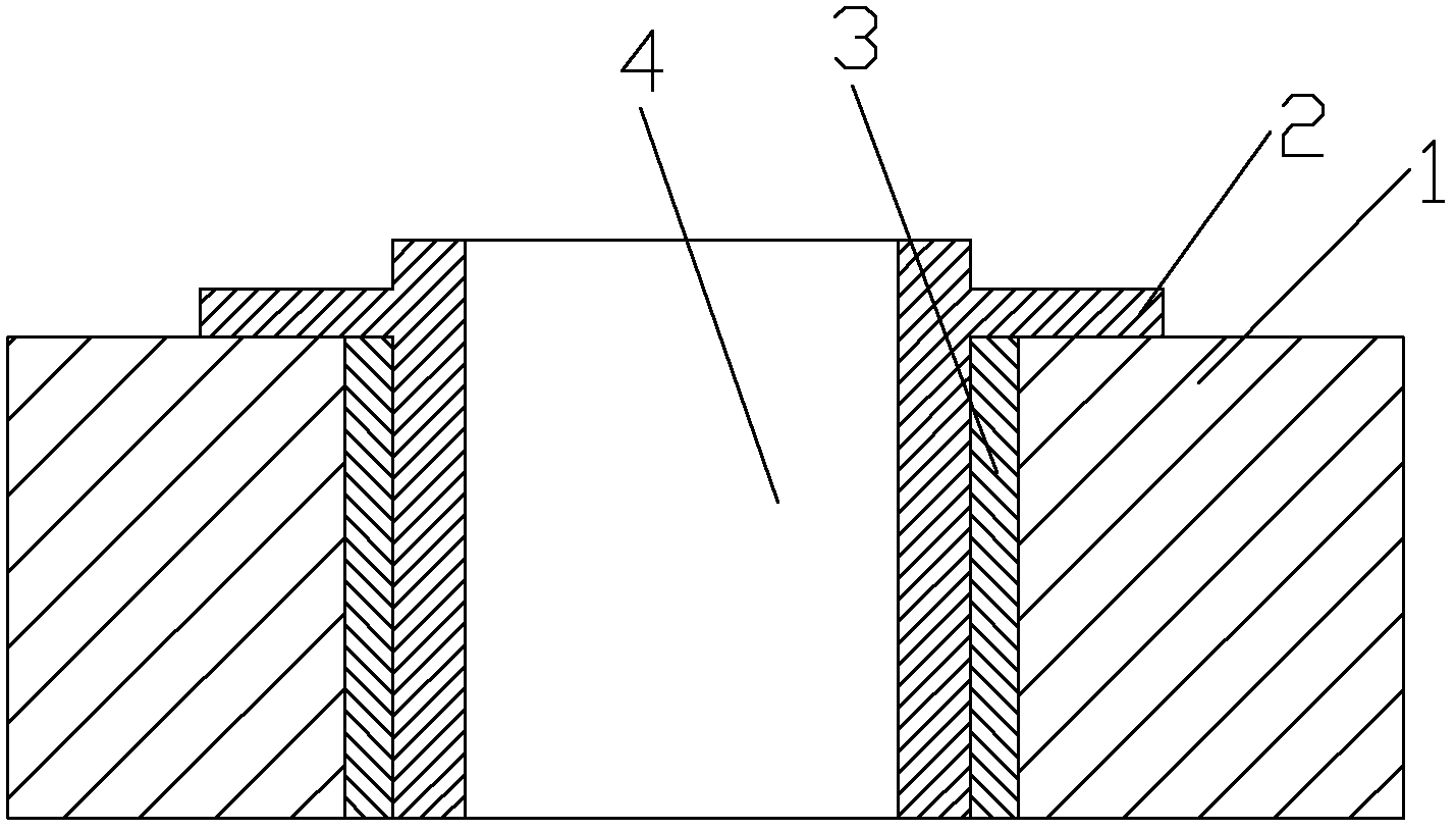
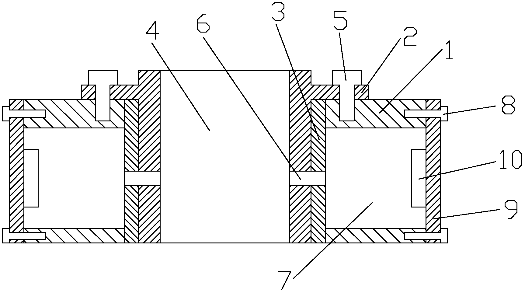
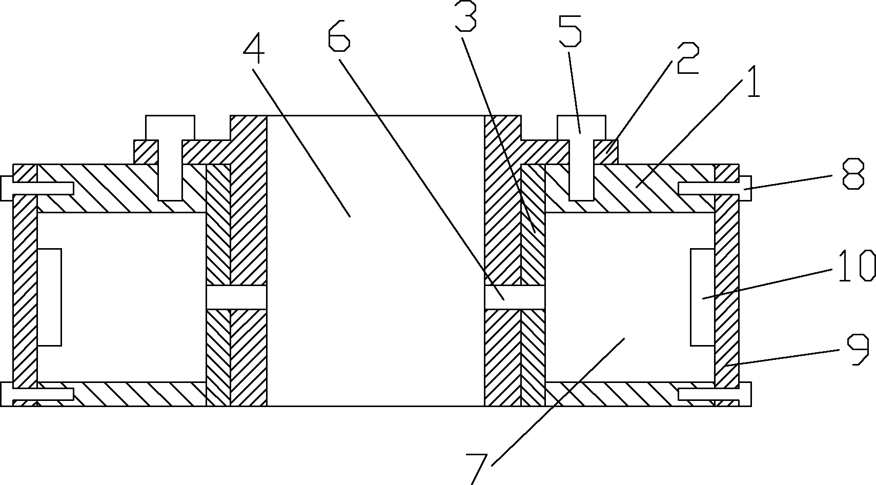
[0014] as attached figure 2 The shown drilling fixture according to the present invention includes a fixture body 1, a guide body 2 and a bushing 3, the fixture body 1 has a mounting hole 4, and the guide body 1 is arranged in the mounting hole 4 , the section of the guide body 1 is "T" shape; the guide body 1 is fixed with the clamp body 1 by the compression spring screw 5; a bushing 3 is arranged between the clamp body 1 and the guide body 2, and the guide body 1 The body 1 and the bushing 3 are left and right symmetrically opened with a chip removal hole 6; the fixture body 1 is provided with a chip slot 7; the chip removal hole 6 communicates with the chip slot 7; the chip slot 7 The outer end is provided with a baffle 9 through a fastener 8; the baffle 9 is provided with a suction device 10. When the drill bit is drilling and produces drill chips into the guide body with the dri...
PUM
 Abstract
Description
Claims
Application Information