Compound hydraulic shifting device

A displacement device and compound technology, applied in the direction of fluid pressure actuating device, etc., can solve the problems of easy wear of the sealing ring and the inability to adjust the output force of the hydraulic cylinder, and achieve the effect of prolonging the service life and replacement cycle and reducing the possibility

Pending Publication Date: 2018-11-30
王沛
View PDF1 Cites 0 Cited by
  • Summary
  • Abstract
  • Description
  • Claims
  • Application Information

AI Technical Summary

Problems solved by technology

[0005] Aiming at the above-mentioned problems that the required oil supply pressure is different, the output force of the hydraulic c

Method used


Image

  • Compound hydraulic shifting device
  • Compound hydraulic shifting device
  • Compound hydraulic shifting device

Examples


Example Embodiment

[0029] The technical solutions of the present invention will be further described and illustrated through specific examples below.

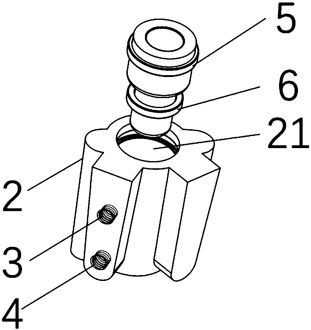
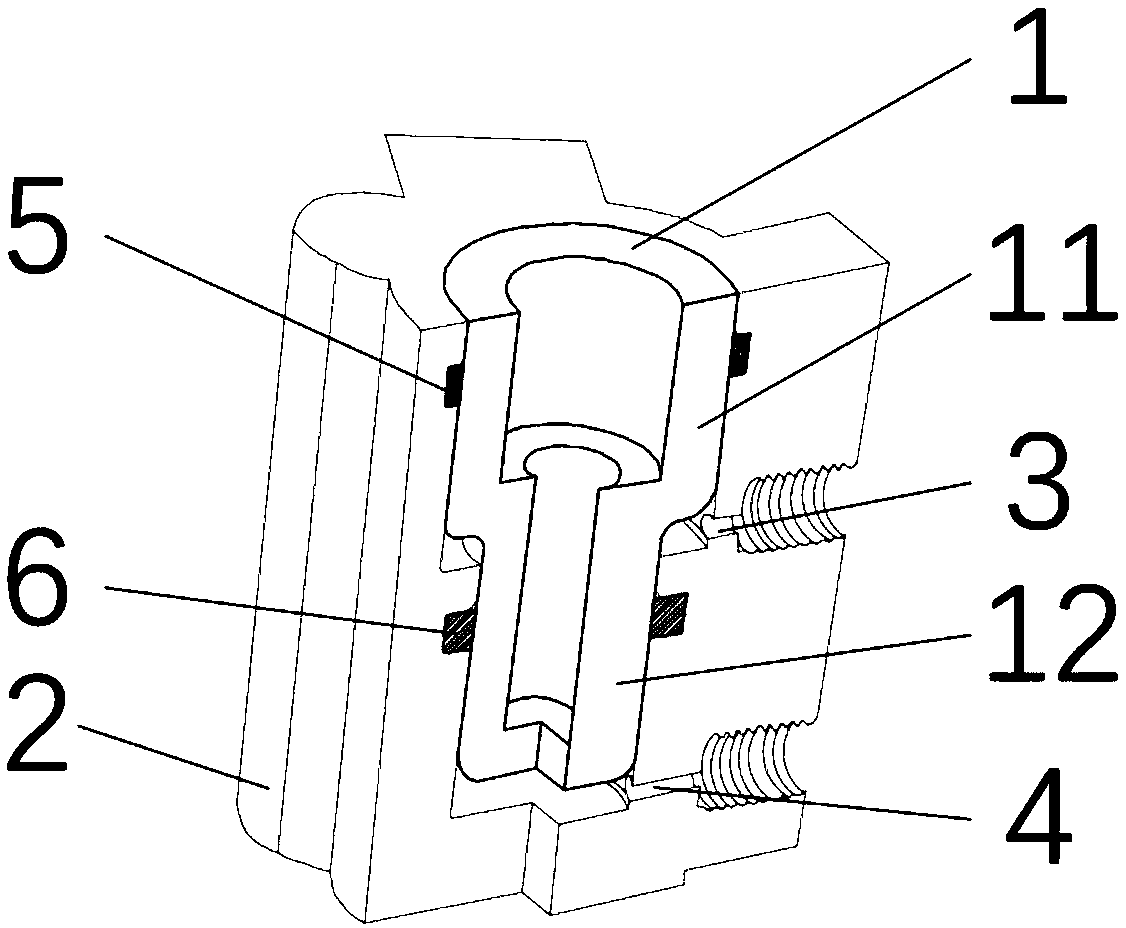
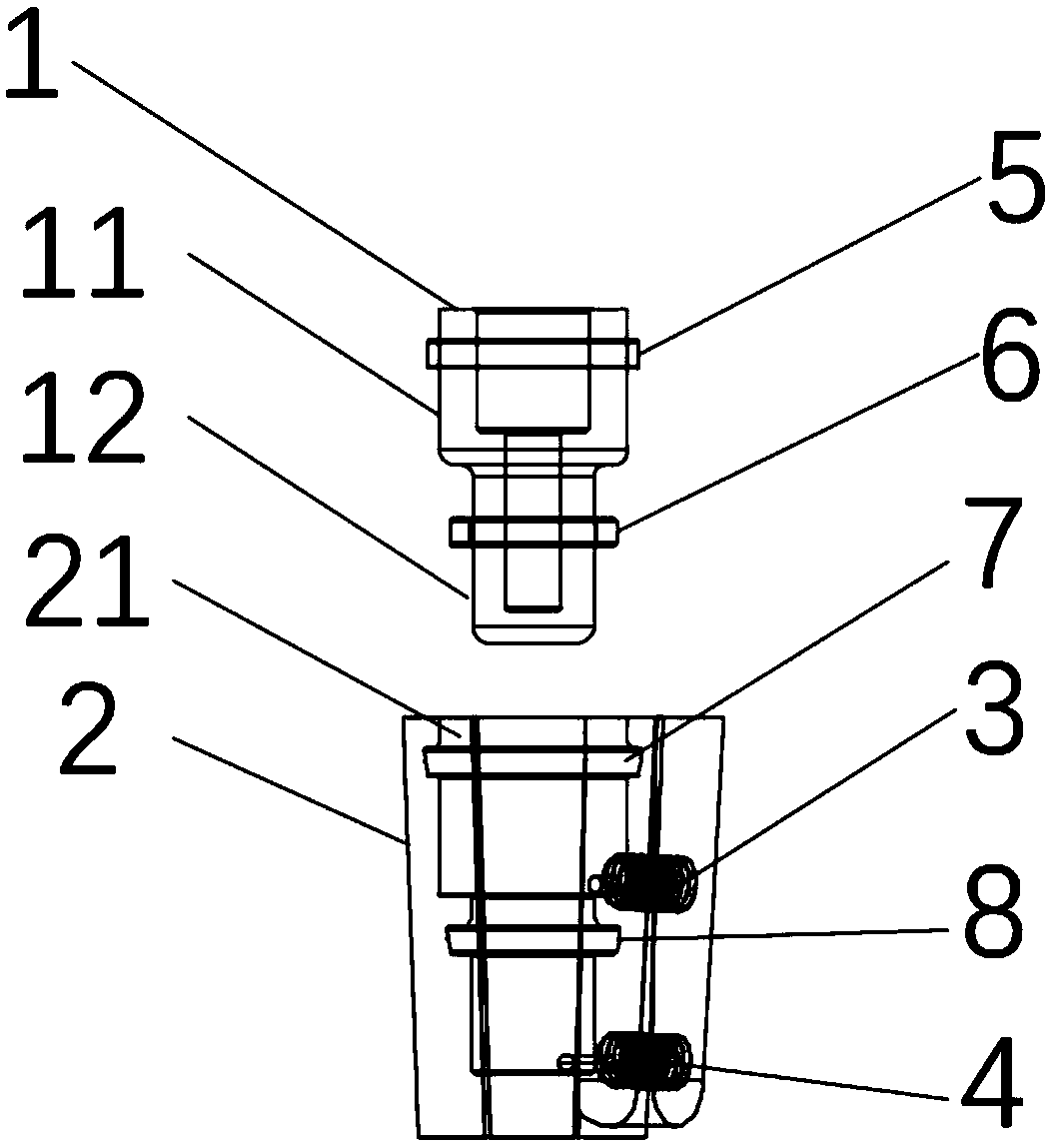
[0030] like Figure 1-8 As shown, the composite hydraulic shifting device includes an oil cylinder body 2 and an oil plug 1 that is movably matched with the oil cylinder body 2. The oil plug 1 includes an upper oil plug 11 and a lower oil plug 12 connected as one, and the outer surface of the upper oil plug 11 The diameter is greater than the outer diameter of the lower oil plug 12, and the oil cylinder body 2 forms an oil plug hole 21 compatible with the oil plug 1, the upper end of the oil plug hole 21 is open, and the lower end is closed. A seal ring 1 5 is provided between the top of the oil plug hole 21 and the upper oil plug 11 , and a seal ring 2 6 is provided between the bottom of the oil plug hole 21 and the lower oil plug 12 . The cylinder body 2 forms an upper oil hole 3 and a lower oil hole 4. The upper oil hole 3 communicates with t...


PUM


Abstract

The invention relates to the technical field of hydraulic oil cylinders, in particular to a compound hydraulic shifting device which comprises an oil cylinder body, and an oil plug movably matched with the oil cylinder body. The oil plug comprises an upper oil plug and a lower oil plug connected into a whole; the outer diameter of the upper oil plug is larger than the outer diameter of the lower oil plug; an oil plug hole adaptive to the oil plug is formed in the oil cylinder body; the upper end of the oil plug hole is opened; the lower end of the oil plug hole is sealed; a seal ring I is arranged between the upper part of the oil plug hole and the upper oil plug; a seal ring II is arranged between the lower part of the oil plug hole and the lower oil plug; an upper oil through hole and alower oil through hole are formed in the oil cylinder body; the upper oil through hole communicates with the upper part of the oil plug hole and the outside; the lower oil through hole communicates with the lower part of the oil plug hole and the outside; the upper oil through hole is formed between the seal ring I and the seal ring II; the lower oil through hole is formed under the seal ring II;and hydraulic oil enters and exits the oil plug hole through the upper oil through hole and/or the lower oil through hole, so that the oil plug stretches out of or is retracted into the oil plug hole.The device can produce different output forces, and the wear of the seal rings is greatly reduced.

Description

technical field [0001] The invention relates to the technical field of hydraulic oil cylinders, in particular to a composite hydraulic displacement device. Background technique [0002] The hydraulic oil cylinder is a hydraulic actuator that converts hydraulic energy into mechanical energy and performs linear reciprocating or oscillating motion. It has a simple structure, reliable operation, and realizes reciprocating motion without a deceleration device. There is no transmission gap and the motion is stable. Therefore, in It is widely used in various mechanical hydraulic systems. The output force of the hydraulic cylinder is proportional to the effective area of ​​the piston and the pressure difference on both sides. The hydraulic cylinder is basically composed of a cylinder, a piston and a sealing device. [0003] In the prior art, the output force of the hydraulic cylinder cannot be adjusted according to the required pressure. When the piston is sealed with the cylinder...

Claims


Application Information

Patent Timeline
IPC IPC(8): F15B15/14F15B15/20
CPCF15B15/14F15B15/1428F15B15/1447F15B15/1452F15B15/20
Inventor 王沛
Owner 王沛
Why Eureka
Try Eureka