Paper-based friction plate feeding manipulator

A paper-based friction disc and manipulator technology, which is applied to manipulators, program-controlled manipulators, chucks, etc., can solve problems such as low work efficiency, achieve compact structure, fast feeding, and expand the scope of application.

Active Publication Date: 2012-07-18
陕西航沣新材料有限公司
View PDF7 Cites 22 Cited by
  • Summary
  • Abstract
  • Description
  • Claims
  • Application Information

AI Technical Summary

Problems solved by technology

[0003] In order to overcome the shortage of low work efficiency caused by the existing three-degree-of-freedom pneumatic manipulator with only one loading and unloading station, the present invention provides a paper-based friction plate feeding manipulator

Method used


Image

  • Paper-based friction plate feeding manipulator
  • Paper-based friction plate feeding manipulator
  • Paper-based friction plate feeding manipulator

Examples


Embodiment Construction

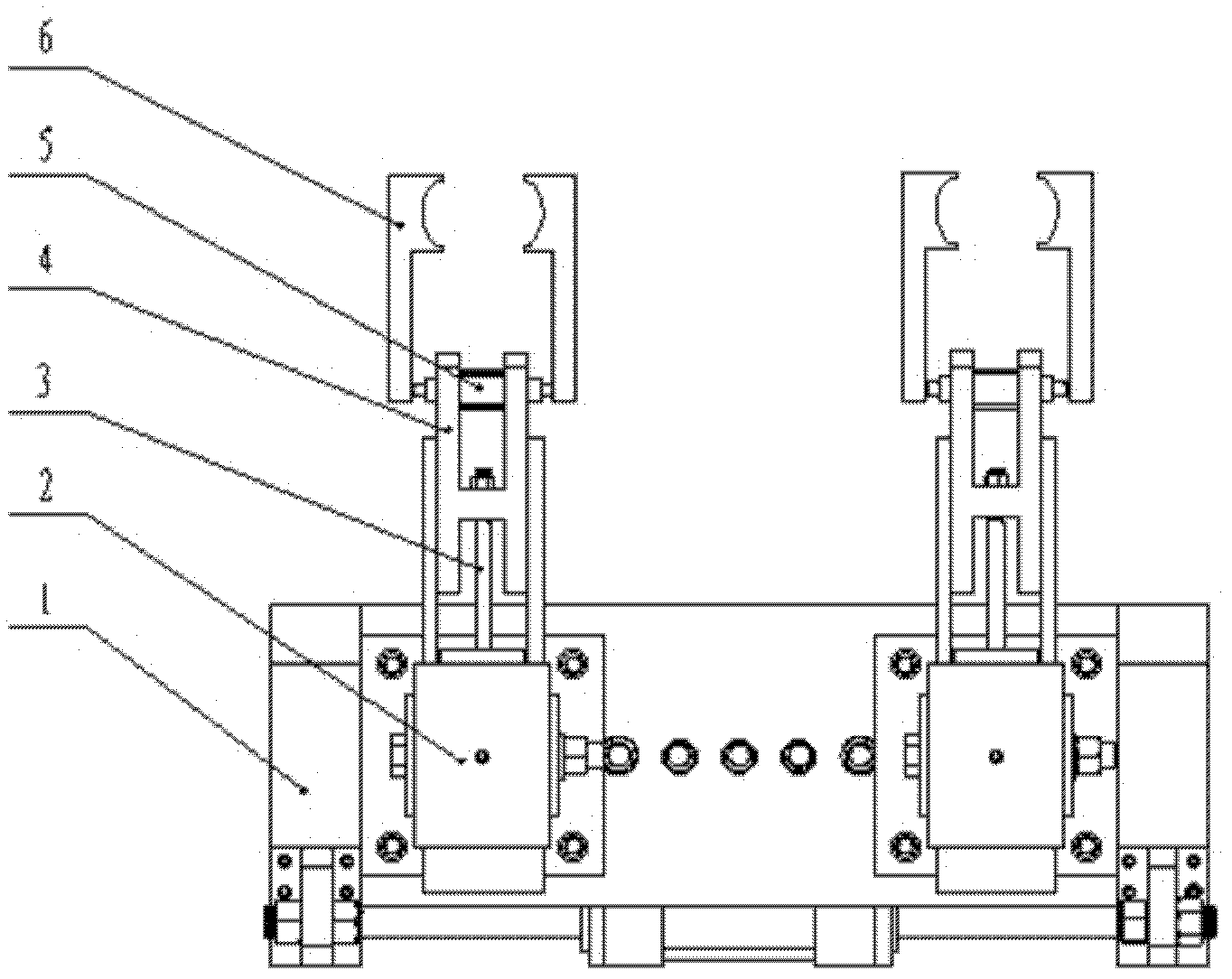
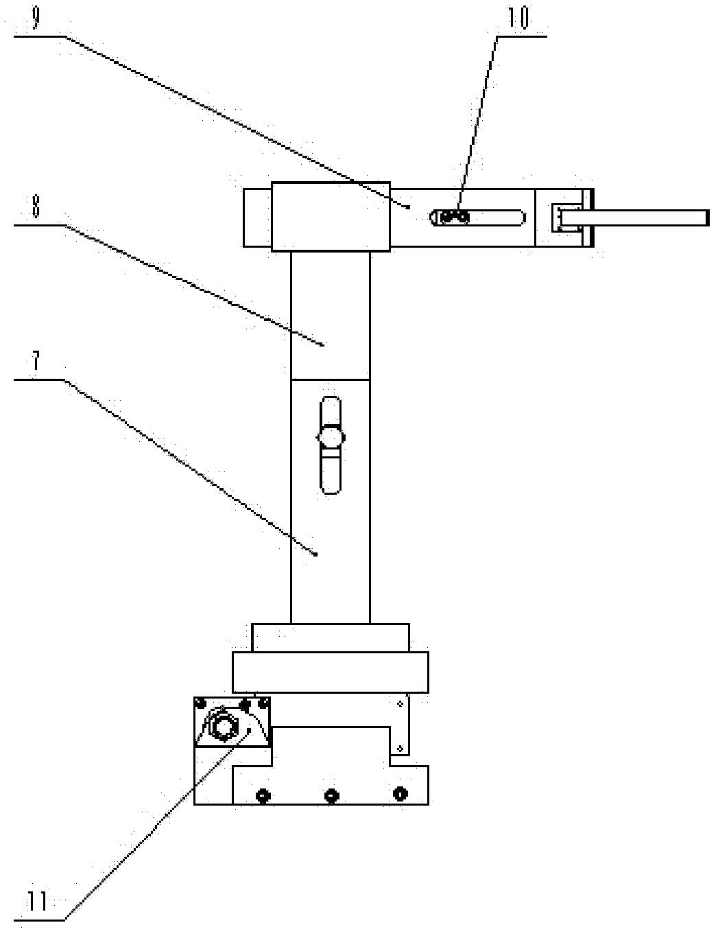
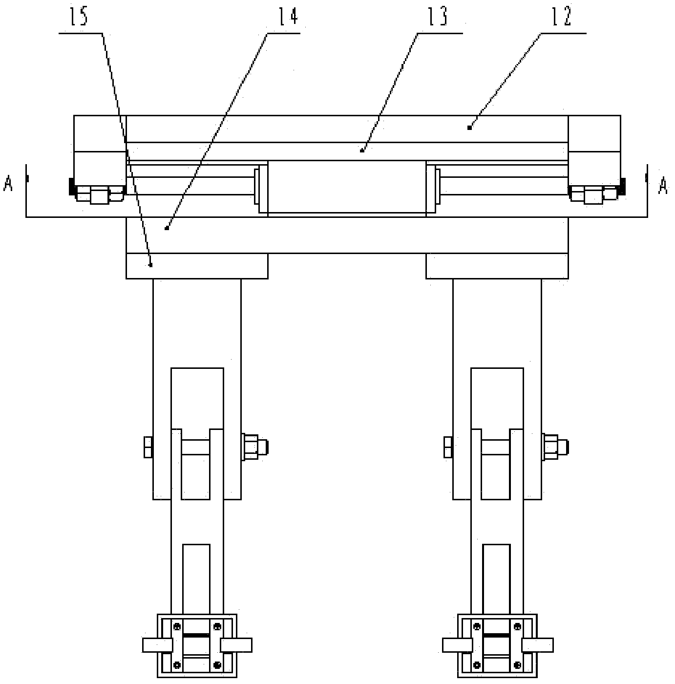
[0015] refer to Figure 1~4 , the paper-based friction sheet feeding manipulator of the present invention includes a bottom block 1, a binding member 2, a longitudinal moving cylinder 3, a horizontal arm connecting plate 4, a manipulator cylinder 5, a manipulator finger 6, a vertical arm 7, a vertical arm joint 8, a horizontal Arm 9, slider 10, piston rod fixing block 11, guide rail fixing plate 12, pneumatic guide rail 13, workbench 14, base 15, slide table 16, flange plate 18. The bottom block 1 is arranged on the two ends of the guide rail fixing plate 12, and the pneumatic guide rail 13 is equal in length to the guide rail fixing plate 12 and is fixedly connected above it; the described slide table 16 is sleeved on the pneumatic guide rail 13, and can Free sliding on the guide rail 13; the slide table 16 is fixedly connected with the horizontal movement cylinder 17 through the flange plate 18, and the piston rod of the horizontal movement cylinder 17 is fixed on the piston...


PUM


Abstract

The invention discloses a paper-based friction plate feeding manipulator, which solves the technical problem of low operating efficiency of an existing three-degree-of-freedom pneumatic manipulator. The technical scheme includes that the paper-based friction plate feeding manipulator comprises a bottom block (1), a combination part (2), a longitudinal moving cylinder (3), a horizontal arm connecting plate (4), manipulator cylinders (5), manipulators (6), vertical arms (7), a vertical arm combination part (8), a horizontal arm (9), a slider (10), a piston rod fixing block (11), a guide rail fixing plate (12), a pneumatic guide rail (13), an operating table (14), a base (15), a sliding table (16), a horizontal moving cylinder (17) and a flange (18). Since two manipulators are parallelly arranged on the operating table, the paper-based friction plate feeding manipulator is suitable for continuous production of gluing and surface mounting of paper-based friction plates. Further, the opening size and all-direction positions of the manipulator are adjustable, gripping of base plates of the paper-based friction plates of different diameters is realized, and operating efficiency is improved.

Description

technical field [0001] The invention relates to a feeding manipulator, in particular to a paper-based friction disc feeding manipulator. Background technique [0002] refer to Figure 5 , the document "Patent No. ZL 200720025499.7 Chinese Invention Patent" discloses a three-degree-of-freedom pneumatic manipulator, which consists of a horizontally moving cylinder 17, a frame 7, a base 15, a motor 6, a horizontally moving guide rod 2, and a pneumatic gripper 11. The vertical lifting cylinder 4, the vertical lifting guide rod 5 and the gear device 8 and 9 are composed. When picking up an object, the horizontal moving cylinder 17 shrinks. Under the guidance of the horizontal moving guide rod 2, the vertical cylinder connecting plate 2 drives the vertical lifting cylinder 4 And the vertical lifting guide rod 5 moves to the left side of the frame 3 shown in the figure, under the effect of the vertical lifting cylinder 4, the vertical lifting guide rod 5 stretches out, the pneumati...

Claims


Application Information

Patent Timeline
Patent Type & Authority Applications(China)
IPC IPC(8): B25J9/08B25J15/00B25J18/00
Inventor 郭学平杨方齐乐华付业伟费杰潘广镇
Owner 陕西航沣新材料有限公司
Why Eureka
Try Eureka