Sanitary phlegm receiving tank

A sanitation box and box top technology, applied in the field of sanitation, can solve problems such as unsanitary, bacteria, and infection

Inactive Publication Date: 2012-07-18
王光树
View PDF4 Cites 0 Cited by
  • Summary
  • Abstract
  • Description
  • Claims
  • Application Information

AI Technical Summary

Problems solved by technology

And people often spit, with bacteria in the sputum, which is

Method used


Image

  • Sanitary phlegm receiving tank
  • Sanitary phlegm receiving tank

Examples


Embodiment Construction

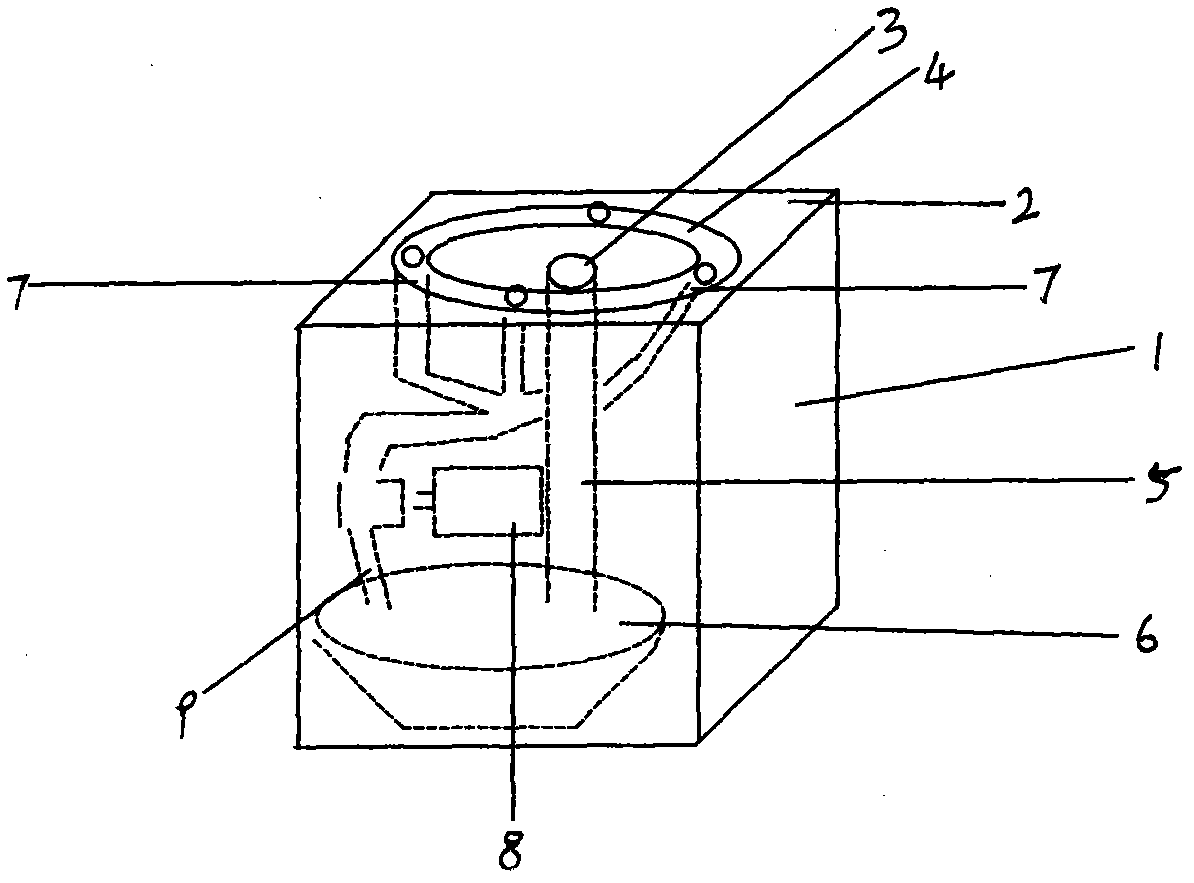
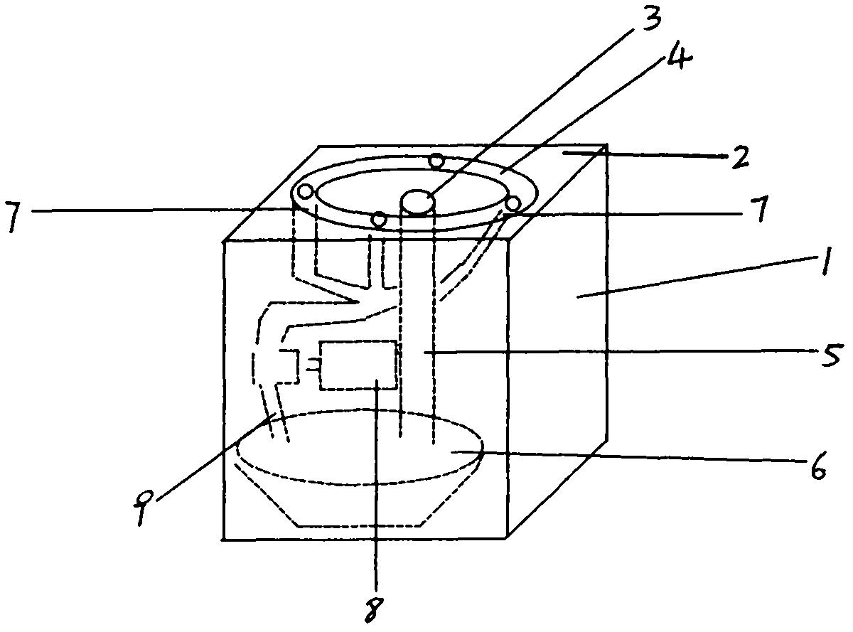
[0008] exist figure 1 Among them, a square box (1) (also can be round), the top of the box (2) facing the upper end is high outside and low inside, and there is a center hole (3) in its center, and there is a circle slightly higher than the center hole (3) around it. ) of the sink (4). The central hole (3) is connected with a pipe (5), which directly leads to a water holding basin (6) or a pond. There are four or more outlet holes (7) in the water tank (4). The orifice of each water outlet hole (7) can have pearl to block in the orifice. Each outlet hole is all connected with the drainpipe of miniature water pump (8). The suction pipe (9) of miniature water pump is placed in the basin (6) of holding water or in the pond. Water pump (8) and basin (6) can be wrapped in the box (1) of square.

[0009] Design principles identical or similar to this patent or to this patent are covered by the protection of this patent.


PUM


Abstract

The invention relates to a sanitary phlegm receiving tank, and belongs to the field of sanitation. The sanitary phlegm receiving tank solves the problems of everywhere splitting and epidemics spread. The center of a square tank (1) is provided with a center hole (3) and a water slot (4). The center hole (3) is connected with a pipe (5) which is communicated to a water containing pan (6) or a pond. The sanitary phlegm receiving tank is used for meeting rooms, streets, stations, docks, schools, markets, factories and families.

Description

technical field [0001] A spitting sanitation box belongs to the field of sanitation. technical background [0002] On the street, in the market, at the station, in the factory and at home, we only see garbage bins, but no sanitary bins for spitting. Some units are better, and we can still see Tanmeng. And people often spit, with bacteria in the sputum, extremely unhygienic, also have infection in the sputum that has. Contents of the invention [0003] A spitting sanitation box is provided here, in which phlegm is spit into the box, which pays attention to hygiene and prevents the spread of diseases. [0004] This invention is like this: a square box (1) (can also be round), the top of the box (2) facing the upper end is high outside and low inside, and there is a central hole (3) in its center, and there is a circle slightly higher than The sink (4) in the center hole (3). The central hole (3) is connected with a pipe (5), which directly leads to a water holding basin ...

Claims


Application Information

Patent Timeline
IPC IPC(8): B65F1/14B65F1/00
Inventor 王光树
Owner 王光树
Why Eureka
Try Eureka