
Self-induction wind-powered lantern

A wind energy and lantern technology, which is applied in lighting devices, with built-in power supply, electric light sources, etc., can solve the problems affecting the application scope and social use value of electroluminescent devices, and achieve low operating costs and beautiful appearance. , the effect of strong reliability

Inactive Publication Date: 2012-07-18
内蒙古能源集团有限公司
View PDF3 Cites 15 Cited by
  • Summary
  • Abstract
  • Description
  • Claims
  • Application Information

AI Technical Summary

Problems solved by technology

At present, the vast majority of public lighting devices, such as street lamps, spotlights, wall lamps, and colorful lights, are all electroluminescent devices. Although they are colorful and have their own characteristics, they all have a common defect, which is the need for external power sources; Once the external power supply is cut off, they will be dimmed; even for solar street lights, their illuminants and daylighting generators are often placed independently, which cannot be regarded as optoelectronic integration in the strict sense, not to mention that all solar light emitting devices are exposed to sunlight. The intensity is affected by the size of the solar panel area. If it is cloudy to cloudy, or the area of ​​the solar panel is as large as a tortoise shell, then everyone can only tacitly understand its luminous effect...
And so on, affect the scope of application and social use value produced by current known electroluminescent devices

Method used


Image

  • Self-induction wind-powered lantern
  • Self-induction wind-powered lantern
  • Self-induction wind-powered lantern

Examples


Embodiment Construction

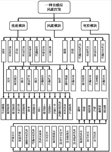
[0044] As a product technical solution, the present invention can be implemented through the organic combination of corresponding modules and parts. The organizational structure between each module and parts of the product of the present invention, such as figure 1 shown.

[0045] figure 1 Among them, the product in the embodiment is composed of three modules: hanger, wind energy, and electric control, and each module is composed of several different parts. The wind energy module consists of tassels, tassels, wind wheel set screws, wind wheel cage, positioning top plate, and wind wheel positioning screws. The electronic control module consists of reverse cone wheel, cone wheel shaft pin, motor set washer, motor set screw, single-phase generator, manual switch, light sensor, manual switch wire, light sensor wire, motor power wire, It consists of thirteen parts including photoelectric controller, ring lamp holder and low-voltage bulb.

[0046] In the implementation process...


PUM


Abstract

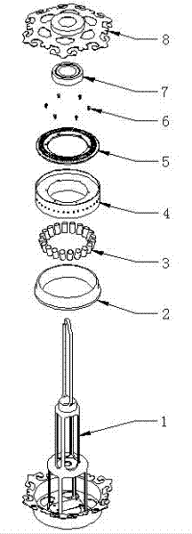
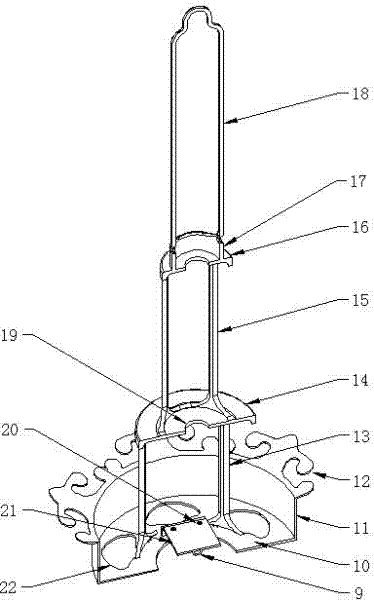
The invention relates to an electric luminous device, particularly relates to a Chinese-style lantern which has a wind power generation function and is capable of controlling luminescence by means of automatically inducting external illumination brightness degree, and provides a self-induction wind-powered lantern. The self-induction wind-powered lantern comprises a hanging seat module, a wind power module and an electric control module and consists of 27 parts including a hanger, roller bases, a variable-speed fluted disc, an auspicious cloud cover, tassels, a tassel stem, a wind wheel lantern body, a positioning top plate, a reverse conical pulley, a single-phase generator, a manual switch, an illumination sensor, a photoelectric controller, an annular lamp holder and the like. Shortcomings that existing electric luminous equipment needs an external power source and does not have national characteristics and the like are overcome, the self-induction wind-powered lantern does not need an external power source, is rich in national characteristics and reliability, emits bright and brilliant lamplight, can be widely used for being hung and used on buildings such as pavilions, corridors of rooms, eaves, door lanes and the like, not only can be used as a daily luminous device, but also can be used as small-sized power generating equipment, can meet service requirements of hotels, government offices, schools and enterprises, is wide in market space, and has high economical added value and social service value.

Description

technical field [0001] The invention relates to an electroluminescent device, in particular to a Chinese-style lantern with its own wind power generation and automatic sensing and control of light from external light. [0002] Background technique [0003] A light-emitting device mainly refers to a vessel or device capable of emitting bright light; an electro-luminescent device refers to a device that emits bright light by using a power source. At present, the vast majority of public lighting devices, such as street lamps, spotlights, wall lamps, and colorful lights, are all electroluminescent devices. Although they are colorful and have their own characteristics, they all have a common defect, which is the need for external power sources; Once the external power supply is cut off, they will be dimmed; even for solar street lights, their illuminants and daylighting generators are often placed independently, which cannot be regarded as optoelectronic integration in the stric...

Claims


Application Information

Patent Timeline
Patent Type & Authority Applications(China)
IPC IPC(8): F21S9/04F21V17/12
Inventor 钟明华
Owner 内蒙古能源集团有限公司
Learn More