
Method for measuring insertion loss of any position of antenna housing

An insertion loss, arbitrary position technology, applied in the field of radome, shipboard radome and satellite communication ground station radome, can solve the problem of complex test system and measurement method, unable to measure the insertion loss of the radome, and affect the insertion loss of the radome Problems such as measurement accuracy, to achieve good promotion and application value, improve measurement accuracy, and simple test system

Inactive Publication Date: 2012-07-18
NO 54 INST OF CHINA ELECTRONICS SCI & TECH GRP
View PDF5 Cites 12 Cited by
  • Summary
  • Abstract
  • Description
  • Claims
  • Application Information

AI Technical Summary

Problems solved by technology

[0003] 1. The traditional far-field method measures the insertion loss of the radome. Since the elevation angle of the transceiver antenna is fixed, the measured insertion loss of the radome is the local insertion loss of a certain elevation angle, and the insertion loss of any position of the radome cannot be measured;
[0004] 2. The insertion loss of the radome is very small, and the conventional far-field method is used for measurement. Due to the limitation of the height of the antenna erection, ground reflection is inevitable, which affects the measurement accuracy of the insertion loss of the radome;
[0005] 3. The traditional far-field method measures the insertion loss of the radome, and the test system and measurement method are complicated

Method used


Image

  • Method for measuring insertion loss of any position of antenna housing
  • Method for measuring insertion loss of any position of antenna housing
  • Method for measuring insertion loss of any position of antenna housing

Examples


Embodiment Construction

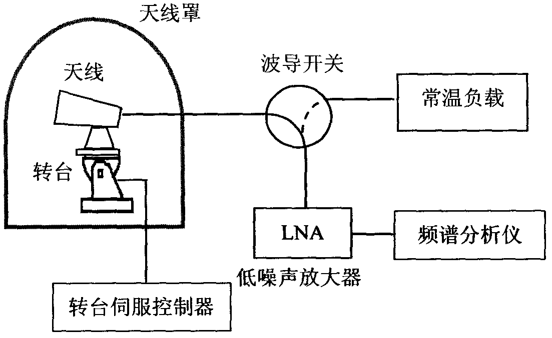
[0030] refer to figure 1 , the test system consists of a radome to be tested, a test turntable, an antenna, a waveguide switch, a low-noise amplifier, a normal temperature load, and a spectrum analyzer. The Y-factor method is used to measure the noise temperature of the antenna with and without a hood. Calculate the size of the residual noise temperature caused by the radome, and thus determine the insertion loss of the radome to be tested.

[0031] attached figure 1 Shown is a schematic diagram of the principle of measuring the insertion loss at any position of the radome. The radome to be tested in the specific embodiment works in the C-band, and the working frequency ranges from 3.4 GHz to 4.2 GHz. The test frequency is 4GHz, the noise temperature T of the low noise amplifier LNA =45K, the noise temperature T of the normal temperature load 0 =293K. Then the radome insertion loss measurement method steps are as follows:

[0032] Step 1: Measure the noise temperature T ...


PUM


Abstract

The invention discloses a method for measuring insertion loss of any position of an antenna housing. When an antenna housing is at any position, the noise temperature of the antenna with or without the housing is measured by an Y-factor method, the residual antenna noise temperature which is caused by the antenna housing is obtained by calculating the difference of the noise temperature of the antenna with or without the housing, and thus, the insertion loss of the antenna housing is determined. The method is simple and practicable and has popularization and application value.

Description

technical field [0001] The invention relates to a radar radome, a ship-borne radome, a satellite communication ground station radome, etc., and is particularly suitable for the measurement of insertion loss at any position of the radome. Background technique [0002] The radome is a kind of dielectric shell used to protect the antenna, so that the antenna can avoid possible damage in various harsh environments, and it is widely used. Such as radar radome, shipboard radome, satellite communication ground station radome, etc. Insertion loss is one of the most important technical indicators of a radome. Usually, the far-field method is used to measure the signal power level received by the antenna with or without a hood, so as to determine the insertion loss of the radome. This method for measuring radome insertion loss has the following limitations: [0003] 1. The traditional far-field method measures the insertion loss of the radome. Since the elevation angle of the transc...

Claims


Application Information

Patent Timeline
Patent Type & Authority Applications(China)
IPC IPC(8): G01R23/16
Inventor 秦顺友武震东梁赞明杜彪张文静邹火儿杜晓恒王聚亮任冀南张志华秦光远李光
Owner NO 54 INST OF CHINA ELECTRONICS SCI & TECH GRP
Learn More