Loop resistance measuring pliers for trolley type switch

A switch circuit and resistance measurement technology, which is applied in the direction of measuring devices, measuring electrical variables, circuit breaker testing, etc., can solve the problems of lower measurement efficiency, low measurement accuracy, troublesome measurement, etc., and achieve improved measurement accuracy and equipment The effect of intact protection and improved measurement efficiency

Inactive Publication Date: 2012-07-18
ZAOZHUANG POWER SUPPLY COMPANY OF STATE GRID SHANDONG ELECTRIC POWER +1
View PDF4 Cites 6 Cited by
  • Summary
  • Abstract
  • Description
  • Claims
  • Application Information

AI Technical Summary

Problems solved by technology

[0003] (1), the measurement accuracy is not high
Only the contacts of the trolley switch are exposed. When measuring the loop resistance, only the cylindrical contacts can be measured. The measuring clamps of the existing measuring instruments are not matched with the equipment. A test failure occurred
[0004] (2), easy to cause damage to the measured equipment
At present, the test current of the switch circuit resistance tester is about 100A. The test clamp of the existing tester is not matched with the switch, and the contact with the main circuit is not tight, which will easily c

Method used


Image

  • Loop resistance measuring pliers for trolley type switch
  • Loop resistance measuring pliers for trolley type switch
  • Loop resistance measuring pliers for trolley type switch

Examples


Embodiment Construction

[0019] The present invention will be further described below in conjunction with accompanying drawing and specific embodiment:

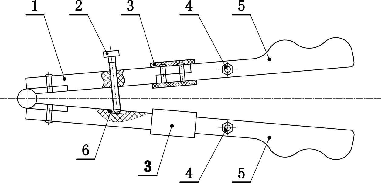
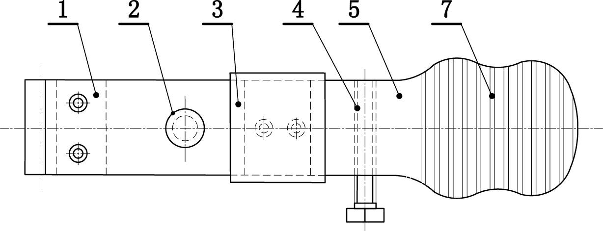
[0020] A trolley type switch circuit resistance measuring clamp, such as figure 1 , figure 2 As shown, the pliers body 1 is included, and the pliers body 1 includes two pins that are hinged to each other. One of the pins of the pliers body 1 is threaded with a tightening bolt 2, and the free end of the tightening bolt 2 is pushed against the other pin of the pliers body 1. On the inner side of the pliers body 1, each foot front end is fixedly connected with a pliers head 5, and each pliers head 5 is provided with an auxiliary contact 4. In this embodiment, a pit 6 is excavated on the inner side of the other foot of the pliers body 1, and the position of the pit 6 corresponds to the expansion bolt 2, and the free end of the expansion bolt 2 rests on the pit 6. Inside. The cross-sectional shape of the front end of the pliers head 5 is a semi-arc sh...


PUM


Abstract

The invention relates to a pair of loop resistance measuring pliers for a trolley type switch, which is good in use effect and safe and reliable. The loop resistance measuring pliers comprises a pliers body, the pliers body comprises two legs hinged with each other. A fastening and expanding bolt is in threaded connection with one of the legs of the pincers body. The free end of the fastening and expanding bolt leans against the inner surface of the other leg of the pincers body. The front end of each leg of the pincers body is fixedly connected with a pincers head. Each pincers head is provided with an assistant contact. A concave pit is excavated inside the other leg of the pincers body. The concave pit corresponds to the fastening and expanding bolt in position. The free end of the fastening and expanding bolt leans against in the concave pit. The cross section of the front end of the pincers head is semi-arc protruding outwards and providing with the concave pit. When the loop resistance measuring pliers is used to measure the loop resistance of the switch, the measuring pincers are placed inside the contact of the trolley type switch to adjust and measure the stretching amplitude of the two legs of the pincers by adjusting the expanding bolt, so that the pincers head of the measuring pincers leans against the inner side of the switch contact, and a switch resistance measuring meter is further connected to the assistant contact of the measuring pincers for measurement.

Description

technical field [0001] The invention relates to an electric device, in particular to a trolley-type switch circuit resistance measuring clamp. Background technique [0002] The existing measuring pliers used for the resistance test of the switch circuit are spring clip type, and the front end of the moving contact of the trolley switch has a circle of contact fingers fixed by the fixing piece and the spring, which is used for the contact of the moving and static contacts. Only when the trolley switch is pushed in Only when the switch cabinet is in the running position can the moving and static contacts be clamped to conduct the conductive circuit. When the switch is pulled out and the loop resistance is measured with spring-clip measuring pliers, the test error is caused by the contact fingers hindering the clamping of the conductive arm by the test pliers, which affects the judgment of the switch performance. The specific deficiencies are as follows: [0003] (1) The meas...

Claims


Application Information

Patent Timeline
IPC IPC(8): G01R31/327G01R27/02
Inventor 姜存磊闫旭张光利张轶鹏吕国栋徐金国李质武吕显斌王坤张维东
Owner ZAOZHUANG POWER SUPPLY COMPANY OF STATE GRID SHANDONG ELECTRIC POWER
Why Eureka
Try Eureka