True surface relief prestack depth domain two-way wave imaging method

An imaging method and true surface technology, applied in the field of seismic exploration, can solve the problems of complex underground structure, complex surface velocity structure, and imaging angle limitation of complex wave field, and achieve the effect of avoiding wave field distortion.

Inactive Publication Date: 2012-07-18
中国石油集团西北地质研究所有限公司
View PDF3 Cites 16 Cited by
  • Summary
  • Abstract
  • Description
  • Claims
  • Application Information

AI Technical Summary

Problems solved by technology

However, the conventional prestack two-way wave imaging technology is based on the horizontal surface for wave field continuation, that is, it is assumed that the receiver points are on the same plane, but in fact the seismic records collected are often on the irregular undulating surface
In the western mountainous region, the surface elevation difference is as high as several thousand meters, in this case, the use of conventional datum imaging technology will lead to incorrect structural morphology due to surface relief
Seismic imaging methods have two main problems in areas with complex surface and complex structures: one is that the surface has large fluctuations and the surface velocity structure is complex; the other is that the underground structure is complex; this double complex structure makes it difficult for seismic imaging methods to accurately image in such areas very big
[0005] In view of the above problems, there will be two major problems to be solved: one is the problem of surface relief in complex areas; the other is the problem of imaging angle limitations in complex wave fields

Method used


Image

  • True surface relief prestack depth domain two-way wave imaging method
  • True surface relief prestack depth domain two-way wave imaging method
  • True surface relief prestack depth domain two-way wave imaging method

Examples


Embodiment 1

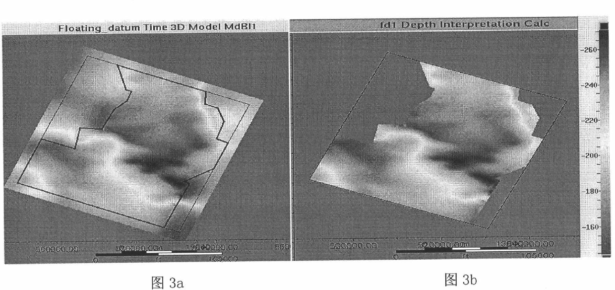
[0051]Seismic recording data with complex surface, complex structure and complex wave field were selected for the test; the surface undulation in the BLH area is relatively large, and the seismic imaging problem in this area is serious due to the complexity of the surface and underground structure, especially for strata with high and steep dip angles greater than 90 degrees The sub-salt structure cannot be imaged, and the sub-salt structure is distorted due to the influence of surface fluctuations and salt dome velocity anomalies; after repeated experiments, the result is that conventional fixed-surface seismic imaging technology cannot solve the problem of accurate imaging in this area. For this reason, we use a two-way wave imaging method in the pre-stack depth domain of true surface relief of the present invention. This method has carried out true surface seismic imaging processing in the BLH Basin. A very good imaging effect has been obtained.

[0052] The two-way wave ima...


PUM


Abstract

The invention discloses a true surface relief prestack depth domain two-way wave imaging method, which specifically comprises the following steps of: (1) acquiring the true surface elevation of a plane with seismic single-shot data by taking the form of a relief surface datum as a basis; (2) redefining a To value, and correcting a speed model; (3) constructing source wavelets, realizing the forward modeling of a source wave field by adopting an optimized difference method, and applying a true surface boundary condition; and (4) performing regular reverse time extrapolation on recorded data along a time direction, applying the relief surface boundary condition, and performing a seismic wave field correlation to acquire a depth domain seismic image. According to the method, the depth domain wave field extrapolation and imaging of the recorded data on a true surface are realized, so that the shortcomings of wave field distortion and untruthful structural form caused by a high surface elevation difference in the conventional technologies can be overcome, and an accurate seismic image and a true geological structural form can be obtained under a complex surface condition.

Description

technical field [0001] The invention relates to the technical field of seismic exploration, in particular to a two-way wave imaging method in the pre-stack depth domain of real surface fluctuations. Background technique [0002] Prestack seismic imaging is a seismic data processing method proposed in the 1970s, including time-domain imaging technology and depth-domain imaging technology; in depth-domain imaging methods, the methods currently used include integration methods based on ray theory and wave theory-based methods. The differential wave equation one-way wave solution method, these two types of methods are difficult to deal with the problem of high-steep-dip-angle structural imaging where the lateral velocity of seismic waves changes drastically. [0003] In recent years, a two-way wave imaging method with higher precision has been developed. This method uses two-way waves to solve the differential wave equation, which theoretically makes up for the imaging defects f...

Claims


Application Information

Patent Timeline
Patent Type & Authority Applications(China)
IPC IPC(8): G01V1/28
Inventor 刘文卿雍学善胡自多王宇超刘红伟曾华会徐新荣
Owner 中国石油集团西北地质研究所有限公司
Why Eureka
Try Eureka