Check patentability & draft patents in minutes with Patsnap Eureka AI!

Electrowetting display unit

An electrowetting display and pixel electrode technology, applied in optical components, optics, instruments, etc., can solve problems such as area increase, leakage, component damage, etc., and achieve the effect of good reliability

Inactive Publication Date: 2012-07-18
WINTEK CORP
View PDF6 Cites 3 Cited by
  • Summary
  • Abstract
  • Description
  • Claims
  • Application Information

AI Technical Summary

Problems solved by technology

However, when the hydrophobicity of the hydrophobic layer is weakened, the area where water directly contacts the hydrophobic layer increases greatly, which may cause leakage.
In this way, the components under the hydrophobic layer will be damaged, and the reliability of the electrowetting display unit will be poor.

Method used


Image

  • Electrowetting display unit
  • Electrowetting display unit
  • Electrowetting display unit

Examples


Embodiment Construction

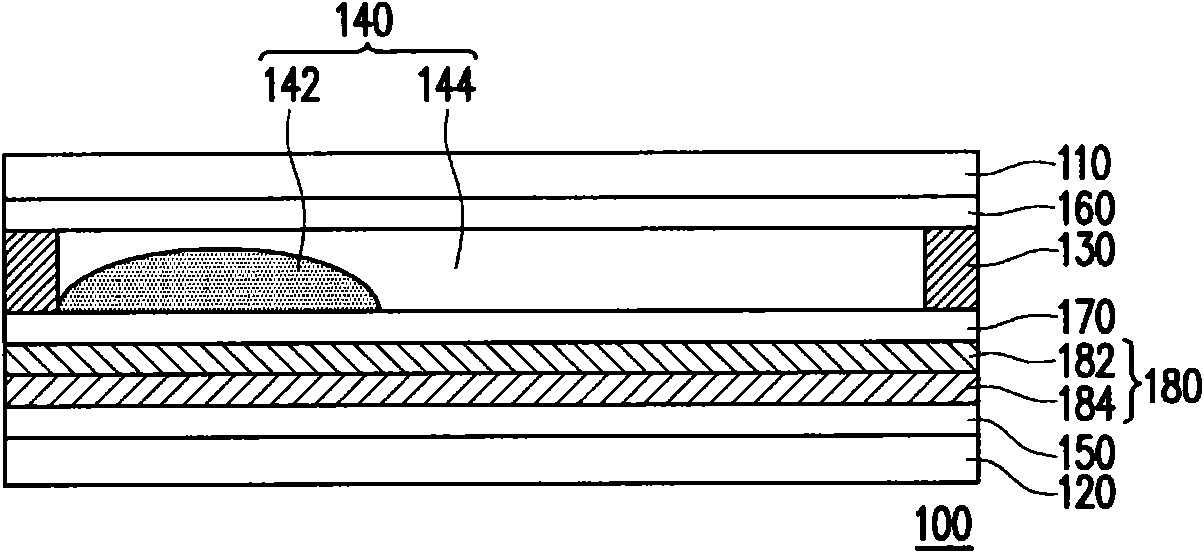
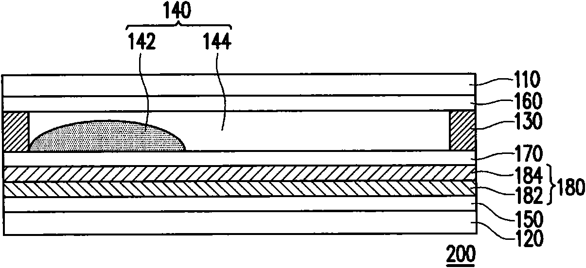
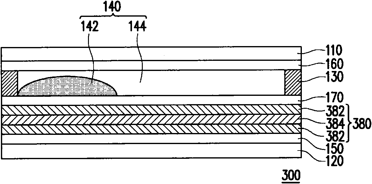
[0035] figure 1 It is a schematic diagram of the electrowetting display unit according to the first embodiment of the present invention. Please refer to figure 1 , the electrowetting display unit 100 includes a first substrate 110, a second substrate 120, a barrier wall 130, an electrowetting display medium 140, a pixel electrode 150, a pair of counter electrodes 160, a hydrophobic layer 170 and a multilayer Insulation structure 180 . The second substrate 120 is opposite to the first substrate 110 . The barrier wall 130 is disposed between the first substrate 110 and the second substrate 120 . The electrowetting display medium 140 is surrounded by the barrier wall 130 , the first substrate 110 and the second substrate 120 . The pixel electrode 150 is disposed between the second substrate 120 and the electrowetting display medium 140 . The opposite electrode 160 is disposed between the first substrate 110 and the electrowetting display medium 140 . The hydrophobic layer 1...


PUM


Abstract

The invention relates to an electrowetting display unit which comprises a first substrate, a second substrate, a retaining wall, an electrowetting display medium, a pixel electrode, a counter electrode, a hydrophobic layer and a multi-layer insulating structure. The second substrate is opposite to the first substrate. The retaining wall is configured between the first substrate and the second substrate. The electrowetting display medium is surrounded by the retaining wall, the first substrate and the second substrate. The pixel electrode is configured between the second substrate and the electrowetting display medium. The counter electrode is configured between the first substrate and the electrowetting display medium. The hydrophobic layer is configured between the pixel electrode and the electrowetting display medium. The multi-layer insulating structure is configured between the pixel electrode and the hydrophobic layer, wherein the multi-layer insulating structure comprises at least one first atomic-layer deposition layer.

Description

technical field [0001] The invention relates to a display element, in particular to an electrowetting display unit. Background technique [0002] With the development and progress of science and technology, the mechanism of electrowetting phenomenon has been understood. The phenomenon of electrowetting mainly utilizes the characteristic that when the applied voltage between two liquids changes, the surface tension also changes, which causes the liquid to move to achieve the desired liquid distribution state. [0003] Electrowetting technology can distribute two liquids of different colors in different ways under the same space, so it can be applied to displays. In detail, the electrowetting display unit has a hydrophobic layer, and the two liquids can be oil and water with different colors. When a voltage is applied to the electrowetting display unit, a charge distribution occurs on the surface of the hydrophobic layer. At this time, the affinity of the hydrophobic layer f...

Claims


Application Information

Patent Timeline
Patent Type & Authority Applications(China)
IPC IPC(8): G02B26/02
Inventor 张劭儒洪钲杰周承毅张恒毅陈君维王志源
Owner WINTEK CORP
Features
  • R&D
  • Intellectual Property
  • Life Sciences
  • Materials
  • Tech Scout
  • Unparalleled Data Quality
  • Higher Quality Content
  • 60% Fewer Hallucinations
Learn More