Luminance testing device

A testing device and technology for brightness, applied in the direction of testing optical performance, optics, instruments, etc., can solve the problems of unsatisfactory brightness test effect, poor mobility and flexibility, etc., and achieve the effect of fast brightness measurement and high practicability

Inactive Publication Date: 2012-07-18
HONG FU JIN PRECISION IND (SHENZHEN) CO LTD +1
View PDF5 Cites 9 Cited by
  • Summary
  • Abstract
  • Description
  • Claims
  • Application Information

AI Technical Summary

Problems solved by technology

Due to the poor mobility and flexibility of most existing luminance test devices, the luminance test results on many existing LCD backlight module production lines are still not ideal

Method used


Image

  • Luminance testing device
  • Luminance testing device
  • Luminance testing device

Examples


Embodiment Construction

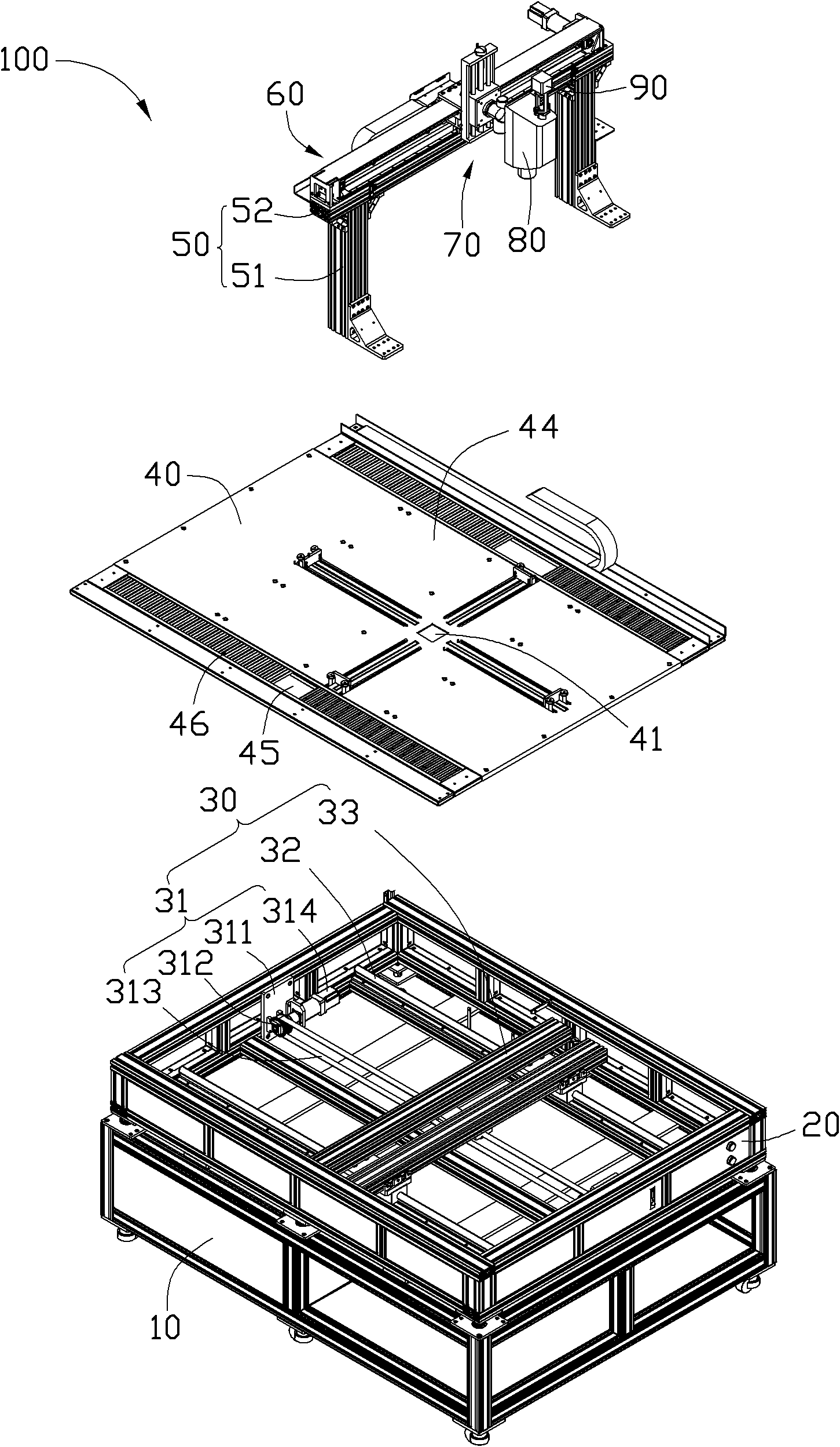
[0015] Please refer to figure 1 A preferred embodiment of the present invention provides a brightness testing device 100 for testing the brightness of a backlight assembly. The luminance testing device 100 includes a base 10, a workbench 20, a first driving mechanism 30, a bearing mechanism 40, a supporting mechanism 50, a second driving mechanism 60, a third driving mechanism 70, a luminance meter 80, and a sensor 90 .

[0016] The base 10 is a rectangular box, and the workbench 20 is a rectangular box with an open top, which is fixedly disposed above the base 10 and is used to house the first driving mechanism 30.

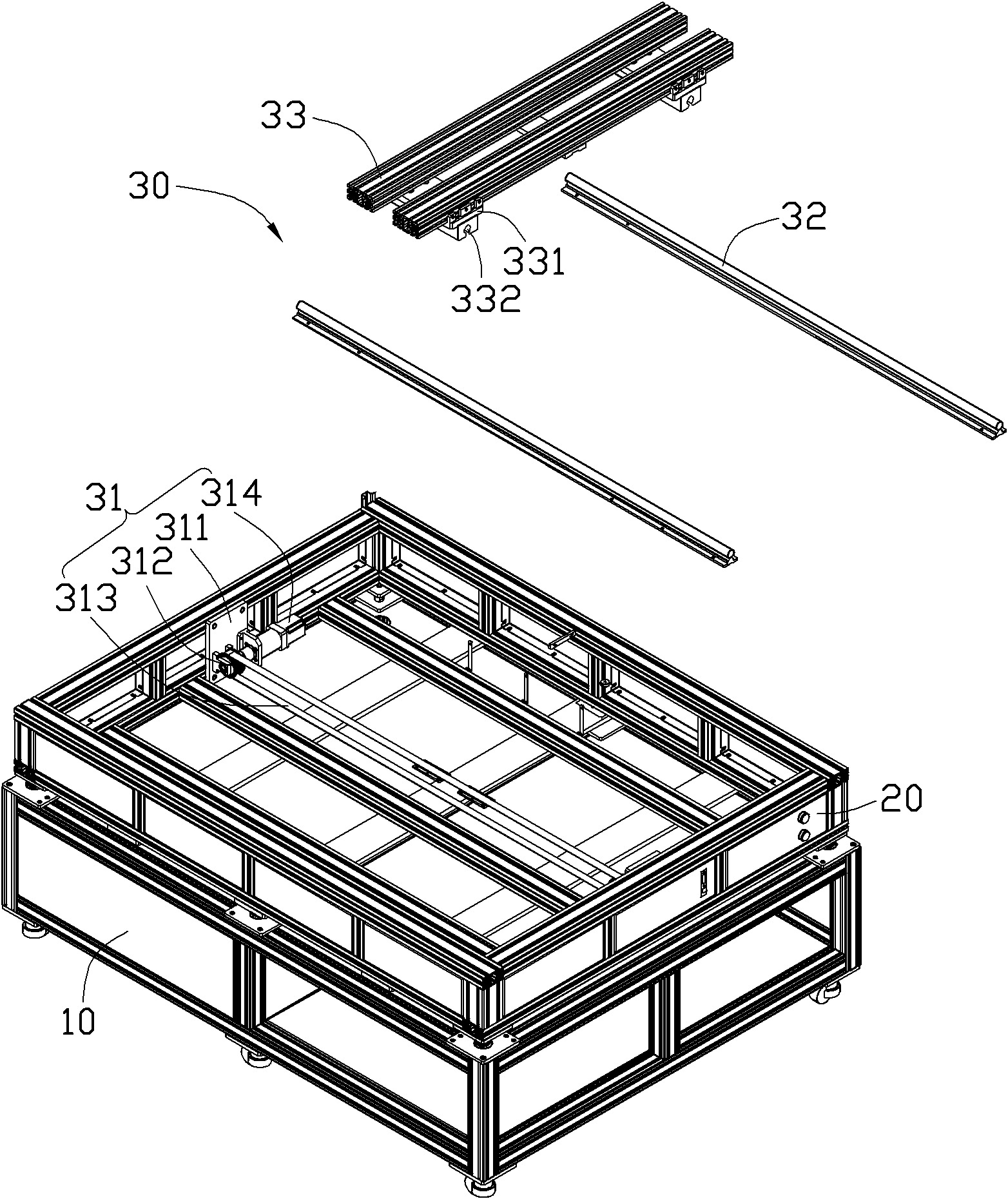
[0017] Please refer to figure 2 , The first driving mechanism 30 includes a first driving part 31, two first sliding rails 32 and two first sliding parts 33. The first driving part 31 includes two first fixing plates 311, two first pulleys 312, a first belt 313 and a first motor 314. The first fixing plate 311 is oppositely arranged in the workbench 20 and perpendi...


PUM


Abstract

The invention provides a luminance testing device. The device comprises a work table, a first driving mechanism, a bearing mechanism, a supporting mechanism, a second driving mechanism, a third driving mechanism and a luminance meter, wherein the work table is used for accommodating the first driving mechanism; the bearing mechanism is covered on the work table and is used for bearing a backlight module; the supporting mechanism is connected to the first driving mechanism and moves left and right along the horizontal direction under the driving of the first driving mechanism; the second driving mechanism is arranged on the support mechanism; the third driving mechanism is arranged at one side of the second driving mechanism; the third driving mechanism is driven by the second driving mechanism to move backwards and forwards along the horizontal direction; and the luminance meter is arranged at one side of the third driving mechanism and is driven by the third driving mechanism to move up and down along the vertical direction.

Description

Technical field [0001] The invention relates to a display test device, in particular to a brightness test device of a display backlight module. Background technique [0002] When the brightness of the light source of the backlight module of the liquid crystal display is uneven, it will cause visual dissonance when the user is watching. Therefore, the brightness of the liquid crystal display needs to be tested during the manufacturing process. Due to the poor mobility and flexibility of most existing luminance test devices, the luminance test effect of many existing LCD backlight module production lines is still not ideal. In order to improve the brightness test accuracy of the LCD backlight module, it is necessary to design a brightness test device with better performance. Summary of the invention [0003] In view of this, it is necessary to provide a brightness test device with higher flexibility. [0004] A brightness testing device for testing the brightness of a backlight ass...

Claims


Application Information

Patent Timeline
Patent Type & Authority Applications(China)
IPC IPC(8): G02F1/13G01M11/02
Inventor 黄登聪胡永兵尚战颜章胜程功水
Owner HONG FU JIN PRECISION IND (SHENZHEN) CO LTD
Why Eureka
Try Eureka