

DC motor with insulating frame structures
A DC motor and insulating frame technology, which is applied in the shape/style/structure of winding insulation, etc., can solve the problems of reducing the winding speed of the motor, reducing the area of the motor slot, and increasing the fullness of the slot, so as to reduce the fullness of the slot and improve the performance, the effect of increasing the motor slot area
Inactive Publication Date: 2012-07-18
MIDEA GRP CO LTD
View PDF5 Cites 10 Cited by
- Summary
- Abstract
- Description
- Claims
- Application Information
AI Technical Summary
Problems solved by technology
[0002] The insulating frame structure of the DC motor currently used has no insulating frame fixing structure. The insulating structure is placed inside the motor casing as a whole, and the wire slots are all placed inside the motor casing, which greatly reduces the area of the motor slot and leads to an increase in slot fullness. , reduce the winding speed of the motor; and the insulation frame does not have a Hall installation position, and the Hall installation is flush, so that the Hall must increase the length of the permanent magnet for effective induction tiles, which increases the cost, and due to the insulation It is very inconvenient to check
Method used
View moreImage
Smart ImageViewing Examples

Examples
Embodiment Construction
Login to View More PUM
 Abstract
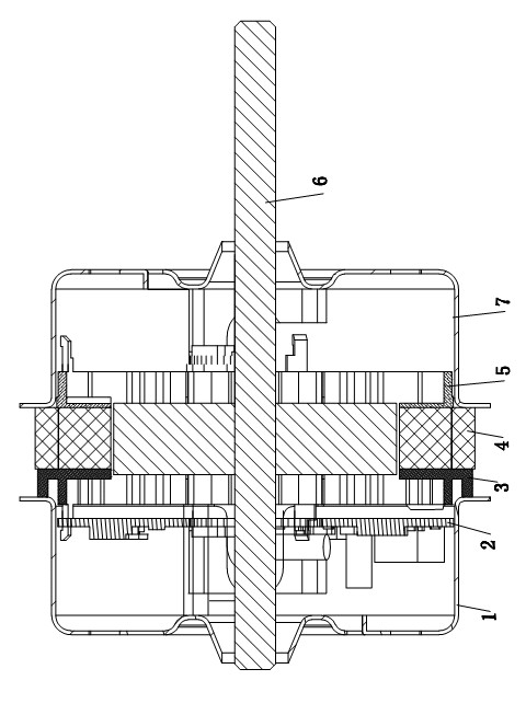
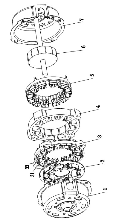
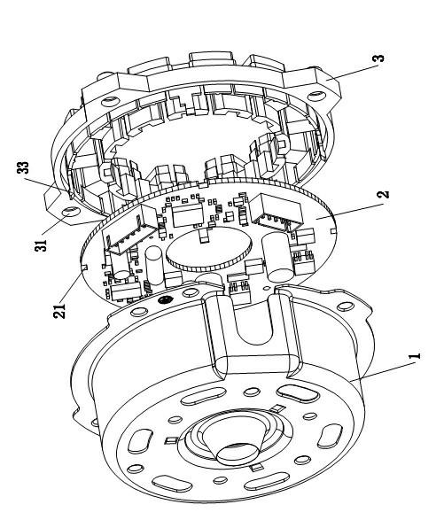
The invention relates to a DC motor with insulating frame structures. The DC motor comprises an upper casing, a control board, an upper insulating frame, a stator iron core, a lower insulating frame, a rotor and a lower casing, wherein the upper and the lower insulating frames are sleeved in the stator iron core; and the upper and the lower casings are matched to form a cavity for mounting the control board, the upper insulating frame, the stator iron core, the lower insulating frame and the rotor. The DC motor is characterized in that the control board is clamped on the upper insulating frame; slots, wire dividing strips, Hall mounting positions, a ring-shaped wire passing slot and fixing positions are arranged on the upper insulating frame; mounting holes are formed on the stator iron core; the fixing positions are embedded into the mounting holes of the stator iron core; the ring-shaped wire passing slot is formed on the edge of the upper insulating frame; the bottom edge of the upper casing is pressed on the ring-shaped wire passing slot; and lug bosses of the upper casing are embedded into the slots of the upper insulating frame. By adopting the DC motor, the mounting concentricity of the insulating frames is improved, and the problem of poor Hall position inductor is solved; and as the ring-shaped wire passing slot is moved to the edge of the upper insulating frame from the inner part of the casing, the area of a motor slot is increased, the slot fill factor can be effectively reduced, and the wire winding speed and the performance of the whole motor can be improved.
Description
technical field [0001] The invention relates to a direct current motor with an insulating frame structure, in particular to a winding structure of a stator iron core suitable for the direct current motor. Background technique [0002] The insulating frame structure of the DC motor currently used has no insulating frame fixing structure. The insulating structure is placed inside the motor casing as a whole, and the wire slots are all placed inside the motor casing, which greatly reduces the area of the motor slot and leads to an increase in slot fullness. , reduce the winding speed of the motor; and the insulation frame does not have a Hall installation position, and the Hall installation is flush, so that the Hall must increase the length of the permanent magnet for effective induction tiles, which increases the cost, and due to the insulation It is very inconvenient when checking. Contents of the invention [0003] The object of the present invention is to provide a ...
Claims
Login to View More Application Information
Patent Timeline
 IPC IPC(8): H02K3/34
Inventor黄坤河廖启国彭颖卿汪志刚杜舜杰
OwnerMIDEA GRP CO LTD