Air cylinder on clutch booster

A booster and clutch technology, which is applied in the direction of clutches, fluid pressure actuating devices, mechanical equipment, etc., can solve the problems of hydraulic cylinder seal ring wear, unstable spring positioning, and insufficient structure of pneumatic cylinders, etc., to achieve concentric installation High precision, wide range of use, good positioning effect

Inactive Publication Date: 2014-10-01
徐月苗
View PDF5 Cites 0 Cited by
  • Summary
  • Abstract
  • Description
  • Claims
  • Application Information

AI Technical Summary

Problems solved by technology

[0003] However, the clutch booster on the market has deficiencies in the structure of the pneumatic cylinder during installation. When in use, the installation is not easy to be on the same axis as the hydraulic cylinder and will be offset, resulting in the sealing ring on the piston of the hydraulic cylinder and the pneumatic cylinder. The sealing ring on the piston is also worn, and oil or air leakage occurs
In addition, when the internal piston is installed, the spring positioning is not stable, resulting in a decrease in the efficiency of the piston after long-term movement, which needs to be improved

Method used


Image

  • Air cylinder on clutch booster

Examples


Embodiment Construction

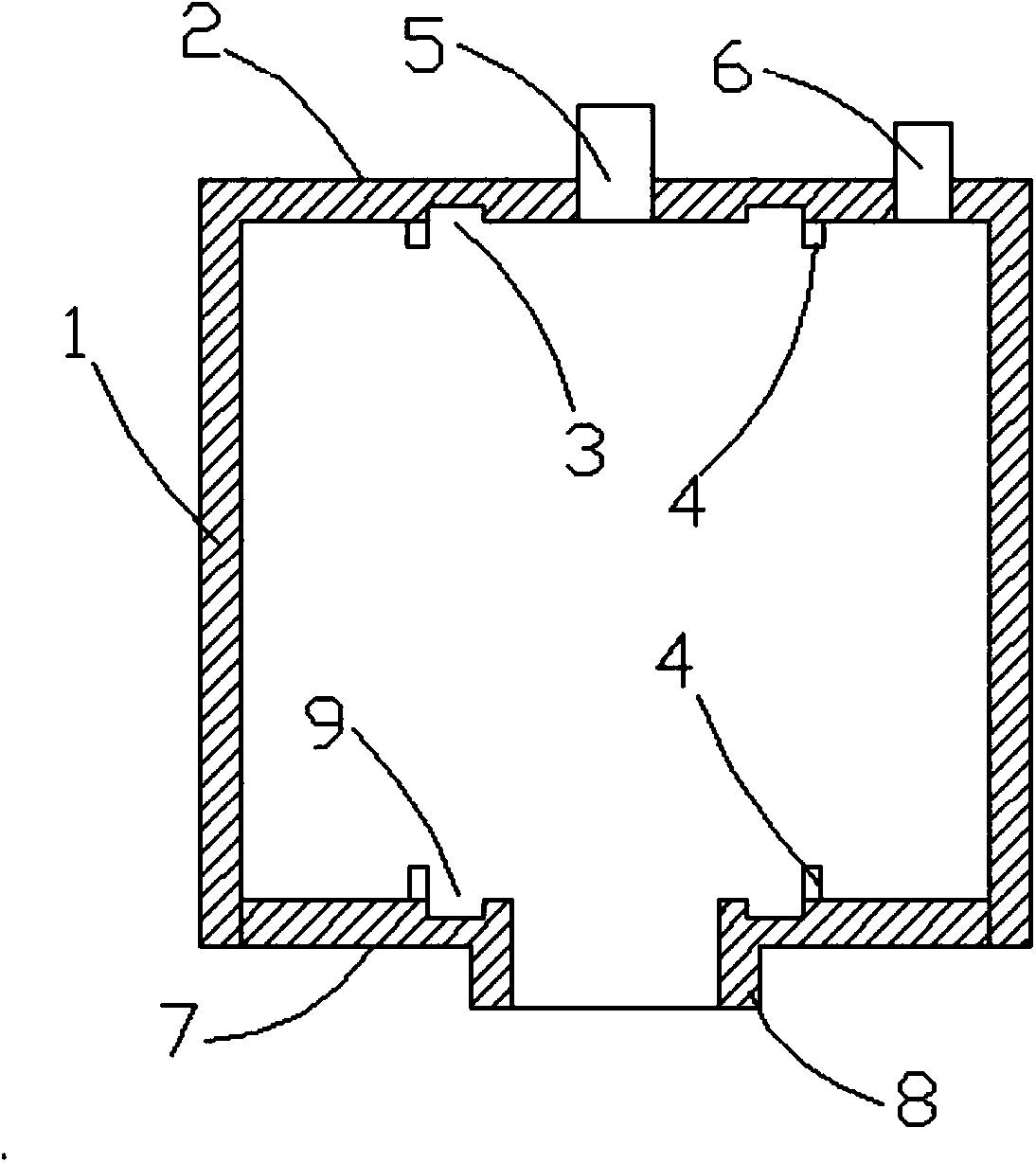
[0019] Such as figure 1 As shown, the present invention relates to a cylinder on a clutch booster, including a cylindrical cylinder block 1, characterized in that: an upper positioning groove 3 is formed on the inner wall of the top surface 2 of the cylinder block 1, and an upper positioning groove 3 is formed on the edge of the upper positioning groove 3 Form 4-8 positioning columns 4 arranged at equal intervals; form a mounting hole 5 in the middle of the top surface 2 of the cylinder block 1, and form a ventilation groove 6 at the outer edge; form an outer protruding outlet end 8 on the bottom surface 7 of the cylinder block 1, A lower positioning groove 9 is formed on the bottom surface 7, and 4-8 positioning columns 4 arranged at equal intervals are formed on the edge of the lower positioning groove 9. The cylinder block 1 is made of aluminum alloy, and the bottom end of the upper positioning groove 3 Form arc groove, be provided with rubber pad in arc groove, the bottom ...


PUM


Abstract

The invention discloses an air cylinder on a clutch booster. The air cylinder on the clutch booster comprises a cylindrical air cylinder body, wherein an upper positioning groove is formed in the inner wall of the top surface of the air cylinder body, four to eight positioning columns which are arranged at equal intervals are arranged on the edge of the upper positioning groove, an installation hole is formed in the middle of the top surface of the air cylinder body, vent grooves are formed in the edge of the outer side of the air cylinder body, an outlet end which protrudes outwards is formed on the bottom surface of the air cylinder body, a lower positioning groove is formed in the bottom surface of the air cylinder body, and four to eight positioning columns which are arranged at equal intervals are arranged on the edge of the lower positioning groove. The air cylinder on the clutch booster has the advantages that the installation concentricity is high, a piston and a spring are well positioned, the application range is wide, and the use performance is improved.

Description

technical field [0001] The invention mainly relates to a clutch control mechanism for automobile transmission, in particular to a cylinder on a clutch booster. Background technique [0002] At present, in the clutch control system of heavy-duty vehicles, buses and construction machinery, due to the heavy force to operate the clutch pedal, the power cannot be cut off in a timely and easy manner, and the gear can be easily shifted. Generally, a clutch booster is installed between the clutch and the clutch master cylinder. The vehicle's compressed air supply powers the clutch. [0003] However, the clutch booster on the market has deficiencies in the structure of the pneumatic cylinder during installation. When in use, the installation is not easy to be on the same axis as the hydraulic cylinder and will be offset, resulting in the sealing ring on the piston of the hydraulic cylinder and the pneumatic cylinder. The sealing ring on the piston is also worn, and oil leakage or ai...

Claims


Application Information

Patent Timeline
Patent Type & Authority Applications(China)
IPC IPC(8): F16D48/04F15B15/20
Inventor 徐月苗
Owner 徐月苗
Why Eureka
Try Eureka