Improved air cylinder used on clutch booster

A booster and clutch technology, applied in clutches, fluid-driven clutches, non-mechanical-driven clutches, etc., can solve the problems of hydraulic cylinder sealing ring wear, unstable spring positioning, insufficient air cylinder structure, etc., and prolong the service life. , good positioning, not easy to offset and shift the effect

Inactive Publication Date: 2014-10-15
陈斌
View PDF6 Cites 0 Cited by
  • Summary
  • Abstract
  • Description
  • Claims
  • Application Information

AI Technical Summary

Problems solved by technology

[0003] However, the clutch booster on the market has deficiencies in the structure of the pneumatic cylinder during installation. When in use, the installation is not easy to be on the same axis as the hydraulic cylinder and will be offset, resulting in the sealing ring on the piston of the hydraulic cylinder and the pneumatic cylinder. The sealing ring on the piston is also worn, and oil or air leakage occurs
In addition, when the internal piston is installed, the spring positioning is not stable, resulting in a decrease in the efficiency of the piston after long-term movement, which needs to be improved

Method used


Image

  • Improved air cylinder used on clutch booster

Examples


Embodiment Construction

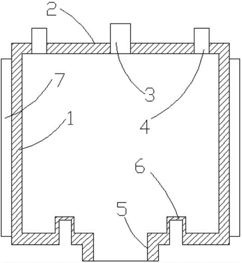
[0018] Such as figure 1 As shown, the present invention relates to an improved cylinder for a clutch booster, comprising a cylindrical cylinder block 1, characterized in that: a mounting hole 3 is formed in the middle of the top surface 2 of the cylinder block 1, and 2 is formed at the outer edge A ventilation slot 4 with the same orientation as the mounting hole 3; an externally protruding outlet end 5 is formed on the bottom surface of the cylinder block 1, and an internally protruding positioning column 6 with internal threads is formed on the bottom surface; Air guide groove, the cylinder block 1 is made of aluminum alloy, the cylinder block 1 is formed by one-time die-casting, the air guide groove 7 is welded on the outer wall of the cylinder block 1, the air guide groove 7 is connected with the cylinder The body 1 is integrally formed, and a hose is connected between the ventilation groove 4 and the air guide groove 7 .

[0019] The above is a detailed introduction to t...


PUM


Abstract

The invention discloses an improved air cylinder used on a clutch booster. The improved air cylinder comprises a barrel-shaped air cylinder body, a mounting hole is formed in the middle of the top surface of the air cylinder body, two ventilating grooves identical with the mounting hole in orientation are formed at the outer-side edge of the air cylinder body, an outwards-protruding outlet end is formed at the bottom surface of the air cylinder body, inwards-protruding positioning columns with internal threads are formed on the bottom surface, two air guide grooves are formed in the outer side wall of the air cylinder body. The improved air cylinder is high in mounting concentricity and efficiency, a piston and a spring are good in positioning and free of displacement, and using performance is improved.

Description

technical field [0001] The invention mainly relates to a clutch control mechanism for automobile transmission, in particular to an improved cylinder used in a clutch booster. Background technique [0002] At present, in the clutch control system of heavy-duty vehicles, buses and construction machinery, due to the heavy force to operate the clutch pedal, the power cannot be cut off in a timely and easy manner, and the gear can be easily shifted. Generally, a clutch booster is installed between the clutch and the clutch master cylinder. The vehicle's compressed air supply powers the clutch. [0003] However, the clutch booster on the market has deficiencies in the structure of the pneumatic cylinder during installation. When in use, the installation is not easy to be on the same axis as the hydraulic cylinder and will be offset, resulting in the sealing ring on the piston of the hydraulic cylinder and the pneumatic cylinder. The sealing ring on the piston is also worn, and oi...

Claims


Application Information

Patent Timeline
Patent Type & Authority Applications(China)
IPC IPC(8): F16D25/12
Inventor 陈斌
Owner 陈斌
Why Eureka
Try Eureka