Improved clutch booster

A technology of booster and clutch, applied in clutch, mechanical equipment, rotational vibration suppression, etc., can solve the problems of clutch booster failure, wear of hydraulic cylinder seal ring piston seal ring, accumulation of dust in cylinder, etc. The effect of improving performance and prolonging service life

Inactive Publication Date: 2014-10-01
徐挺
View PDF5 Cites 0 Cited by
  • Summary
  • Abstract
  • Description
  • Claims
  • Application Information

AI Technical Summary

Problems solved by technology

[0003] However, due to the fact that the clutch booster on the market is not coaxial between the hydraulic cylinder and the pneumatic cylinder during installation, there will be an offset between them during use, resulting in the hydraulic cylinder, the sealing ring on the pneumatic cylinder piston and the piston on the piston. The sealing ring is also worn, and there is oil leakage or air leakage
[0004] In addition, because the setting position of the clutch booster is relatively low from the ground, the clutch booster is in a dust-intensive environment, which will inhale a large amount of dust under the respiration generated by the reciprocating motion of the cylinder piston, and then form the dust inside the cylinder. Accumulate a large amount of dust, which will eventually condense into blocks and affect the use. Blocky objects can easily scratch the cylinder block and seals, resulting in failure of the clutch booster

Method used


Image

  • Improved clutch booster

Examples


Embodiment Construction

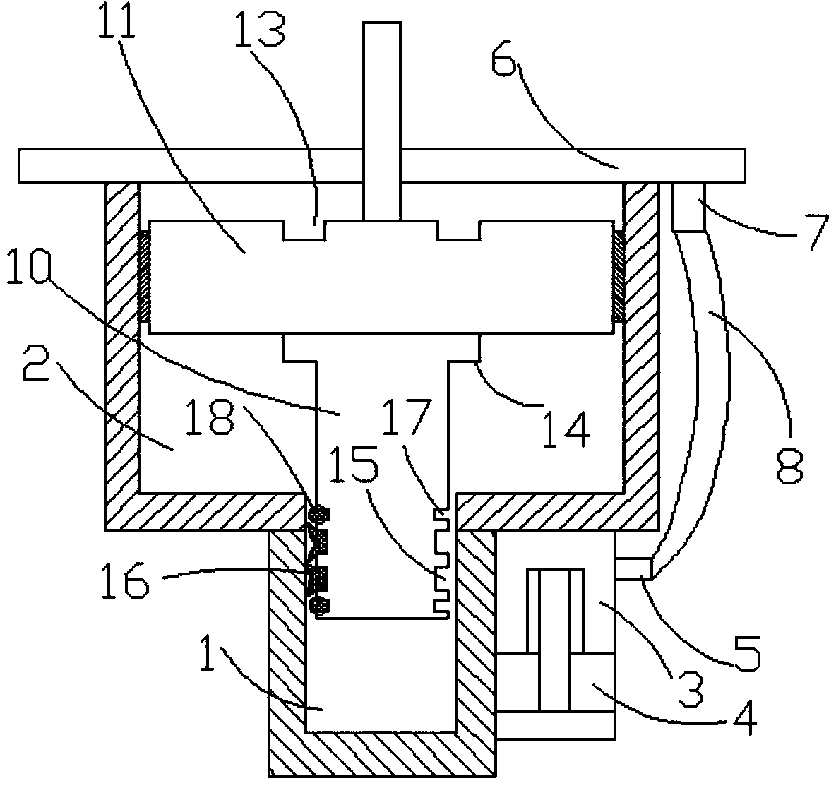
[0019] Such as figure 1 As shown, the present invention relates to an improved clutch booster, which is characterized in that it includes a hydraulic cylinder 1 on the same axis and a pneumatic cylinder 2 arranged on the hydraulic cylinder 1, and a small cavity is provided on the same plane of the hydraulic cylinder 1 body 3, the small cavity 3 is provided with a small piston 4 with a vent hole, the small cavity 3 is provided with a vent outlet 5, and the front cover plate 6 of the pneumatic cylinder 2 is provided with a vent pipe 7, so A flexible pipe 8 is provided between the air outlet 5 and the air pipe 7, the hydraulic cylinder 1 and the pneumatic cylinder 2 are connected as an integral structure, and a piston is arranged in the air cylinder 2 and the hydraulic cylinder 1, and the piston includes a piston The rod 10 and the piston end 11 are provided with a rubber guide sleeve 12 on the outer wall of the piston end 11, the top end forms a positioning ring groove 13 for fi...


PUM


Abstract

The invention discloses an improved clutch booster which comprises a hydraulic cylinder and a pneumatic cylinder. The hydraulic cylinder and the pneumatic cylinder share the same axis, the pneumatic cylinder is arranged on the hydraulic cylinder, a small cavity is arranged on the same plane as the pneumatic cylinder, a piston with a venting hole is arranged in the small cavity, a venting outlet is formed in the small cavity, a venting pipe is arranged on a front cover plate of the pneumatic cylinder, a flexible pipe is arranged between the venting outlet and the venting pipe, the hydraulic cylinder and the pneumatic cylinder are connected into an integrated structure, and pistons are arranged in the pneumatic cylinder and the hydraulic cylinder. Each piston comprises a piston rod and a piston end, wherein a rubber guide sleeve is arranged on the outer wall of the piston end, a locating annular groove for fixing a spring is formed in the upper end of the piston end, an annular protruded body is formed at the bottom end of the piston end, two annular clamping grooves which are arranged at interval are formed in the piston rod, and Y-shaped sealing rings are arranged in the annular clamping grooves. The improved clutch booster effectively solves the corrosion problem, reduces manufacturing cost, is high in installation concentricity, reduces corrosion of sealing parts, meanwhile effectively prevents dust from entering and protects internal elements.

Description

technical field [0001] The invention mainly relates to a clutch control mechanism for automobile transmission, in particular to an improved clutch booster. Background technique [0002] At present, in the clutch control system of heavy-duty vehicles, buses and construction machinery, due to the heavy force to operate the clutch pedal, the power cannot be cut off in a timely and easy manner, and the gear can be easily shifted. Generally, a clutch booster is installed between the clutch and the clutch master cylinder. The vehicle's compressed air supply powers the clutch. [0003] However, because the clutch booster on the market is not coaxial between the hydraulic cylinder and the pneumatic cylinder during installation, there will be an offset between them during use, resulting in the hydraulic cylinder, the sealing ring on the pneumatic cylinder piston and the piston on the piston. The sealing ring is also worn out, and oil leakage or air leakage occurs. [0004] In addit...

Claims


Application Information

Patent Timeline
Patent Type & Authority Applications(China)
IPC IPC(8): F16D48/04F16F15/16
Inventor 徐挺
Owner 徐挺
Why Eureka
Try Eureka