Piezoelectric power generation device based on excitation of fluidic micro oscillator

A piezoelectric power generation and power generation device technology, applied in piezoelectric effect/electrostrictive or magnetostrictive motors, generators/motors, electrical components, etc., can solve the trouble of replacing batteries, energy waste, limited battery energy, etc. problem, to achieve the effect of improving the utilization efficiency, eliminating the need to replace the battery, and having a simple structure

Inactive Publication Date: 2012-07-18
TSINGHUA UNIV
3 Cites 44 Cited by

AI-Extracted Technical Summary

Problems solved by technology

[0002] At present, in the pneumatic industry, the exhaust gas discharged from pneumatic components (cylinders, vacuum generators, etc.) is usually directly discharged into the atmosphere, resulting in a great...

Method used

The first output port 10 of the described bistable jet element is communicated with the air inlet 3 of the first oscillation cavity, and the air outlet 7 of the first oscillation cavity is communicated with the first control port 12 of the bistable jet element; the described The second output port 11 of the bistable jet element communicates with the air inlet of the se...

Abstract

The invention discloses a piezoelectric power generation device based on the excitation of a fluidic micro oscillator. The device comprises a housing, a bistable fluidic element, a first oscillation cavity, a second oscillation cavity and an output circuit, wherein the first and the second oscillation cavities are symmetrically distributed on the left side and the right side of the bistable fluidic element; diaphragm patches are respectively arranged on the first and the second oscillation cavities; piezoelectric patches are arranged on the diaphragm patches; and a gas inlet of the bistable fluidic element is communicated with a gas exhaust opening of pneumatic equipment. Due to a wall attaching effect of the bistable fluidic element, gas repeatedly circulates in the oscillation cavities on the two sides of the device to form oscillation gas, an oscillation gas flow in the oscillation cavities drives the diaphragm patches on cavity chambers to vibrate, and the vibration of the diaphragm patches drives the piezoelectric patches thereon to vibrate and deform to produce electric charge. By using the device, a waste gas energy resource can be converted into electric energy, power can be supplied to a wireless sensor, the trouble of battery replacement is saved and the energy source utilization efficiency is improved. The device has the advantages of simple structure, energy conservation and environmental friendliness, and is convenient to implement.

Application Domain

Technology Topic

Image

  • Piezoelectric power generation device based on excitation of fluidic micro oscillator
  • Piezoelectric power generation device based on excitation of fluidic micro oscillator
  • Piezoelectric power generation device based on excitation of fluidic micro oscillator

Examples

  • Experimental program(1)

Example Embodiment

[0011] The specific structure, principle and working process of the present invention will be described in detail below with reference to the accompanying drawings.
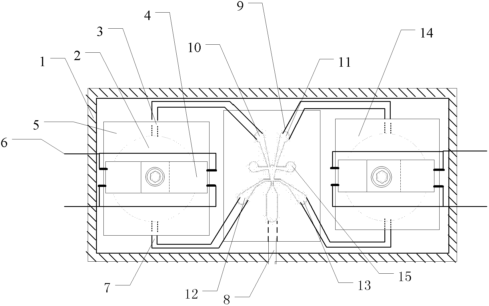
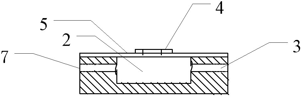
[0012] Such as figure 1 As shown, the piezoelectric power generation device based on jet micro-oscillator excitation provided by the present invention includes a housing 1, a bistable jet element 9, a first oscillation cavity 2, a second oscillation cavity 14 and an output circuit 6. The bistable jet element 9 is installed in the middle of the bottom of the housing 1, and the first oscillation cavity 2 and the second oscillation cavity 14 are symmetrically installed on the left and right sides of the bistable jet element. The bistable jet element 9 is provided with a bistable jet element air inlet 8, a bistable jet element first output port 10, a bistable jet element second output port 11, a bistable jet element first control port 12, and a bistable jet element. The jet element second control port 13 and the bistable jet element exhaust port 15.
[0013] The first output port 10 of the bistable jet element communicates with the air inlet 3 of the first oscillation cavity, and the outlet hole 7 of the first oscillation cavity communicates with the first control port 12 of the bistable jet element; The second output port 11 of the element is in communication with the air inlet of the second oscillation cavity, and the outlet of the second oscillation cavity is in communication with the second control port 13 of the bistable jet element; the air inlet 8 of the bistable jet element is connected with the exhaust of the pneumatic equipment 口通。 Mouth connected. The output circuit 6 is arranged above the bistable jet element, so that its structure is neat and compact.
[0014] figure 2 It is a schematic diagram (cross-sectional view) of the structure principle of the oscillating cavity. A diaphragm 5 is provided on the first oscillating cavity and the second oscillating cavity, and a piezoelectric sheet 4 is provided on the diaphragm.
[0015] The bistable jet element 9 is composed of a bistable jet element core plate 18, a bistable jet element upper cover plate 16 and a bistable jet element lower bottom plate 17. The upper cover plate and the lower bottom plate are made of organic glass plates, which are mainly used for bistable jet elements. The sealing of the jet element; the upper cover plate corresponds to the core plate with round holes at the entrance and Figure 3a , 3b , 3c).
[0016] The working process of the present invention is as follows:
[0017] The exhaust holes of pneumatic equipment such as vacuum generators and air cylinders are connected with the air intake holes 8 of the bistable jet element. The gas enters the bistable jet element through the air inlet. Due to the wall effect of the bistable jet element, the gas is output from the first output port 10 of the bistable jet element. Part of the gas is discharged from the exhaust hole 15 of the bistable jet element. Enter the first oscillating cavity 2 and then return to the first control port 12 of the bistable jet element, so that the gas is switched to the other side of the bistable jet element, and is output from the second output port 11 of the bistable jet element. Exhaust from the vent hole 15 of the bistable jet element, another part of the gas enters the second oscillating cavity 14, and then returns to the second control port 13 of the bistable jet element, so that the gas faces the other side of the attached wall again, and repeats the cycle on both sides. Oscillations formed in the chamber. The oscillating gas in the chamber drives the diaphragm 5 to vibrate, and the vibration of the diaphragm drives the piezoelectric sheet 4 mounted on it to vibrate and deform to generate a voltage. The output circuit 6 outputs the voltage generated by the piezoelectric sheet to provide power for micro devices.

PUM

no PUM

Description & Claims & Application Information

We can also present the details of the Description, Claims and Application information to help users get a comprehensive understanding of the technical details of the patent, such as background art, summary of invention, brief description of drawings, description of embodiments, and other original content. On the other hand, users can also determine the specific scope of protection of the technology through the list of claims; as well as understand the changes in the life cycle of the technology with the presentation of the patent timeline. Login to view more.

Similar technology patents

Art for producing soyabean polypeptide powder without bitter taste

InactiveCN1461597AShorten the enzymatic digestion timeImprove utilization efficiencyProtein composition from vegetable seedsActivated carbonKaolinite
Owner:瑞泰高直生物科技(武汉)有限公司

Double chelate compound fertilizer

Owner:SHANDONG CHUNYU FERTILIZER IND

Classification and recommendation of technical efficacy words

Why Eureka
Try Eureka