
Multi-antenna transmission system and method

A multi-antenna transmission and antenna selection technology, applied in the field of mobile communication, can solve the problems of radio frequency link redundancy, etc., and achieve the effect of reducing system cost and number

Inactive Publication Date: 2012-07-18
UNIV OF ELECTRONICS SCI & TECH OF CHINA
View PDF4 Cites 12 Cited by
  • Summary
  • Abstract
  • Description
  • Claims
  • Application Information

AI Technical Summary

Benefits of technology

This technology allows multiple radios (transmitting) devices within range to communicate wirelessly without having them all working together at once - instead relying on one device's own communication capabilities. It divides up each piece of information that needs to travel across different paths before reaching its destination where it can use this divided signal. By doing things like transmitting signals over separate wires or wireless networks, fewer radiofrequency chains are needed while still maintaining their effectiveness.

Problems solved by technology

This patented describes how spatial modulated techniques help improve wireless networks' performance without requiring more expensive equipment than what was previously possible due to their limitations on communicating resource allocation. These improvements include improved signal quality at different frequencies for better reception even with fewer receivers while also reducing costs associated with longer connections between devices.

Method used


Image

  • Multi-antenna transmission system and method
  • Multi-antenna transmission system and method
  • Multi-antenna transmission system and method

Examples


Embodiment Construction

[0035] Specific embodiments of the present invention will be given below in conjunction with the accompanying drawings.

[0036] Before setting forth the specific implementation, first introduce the terms used therein:

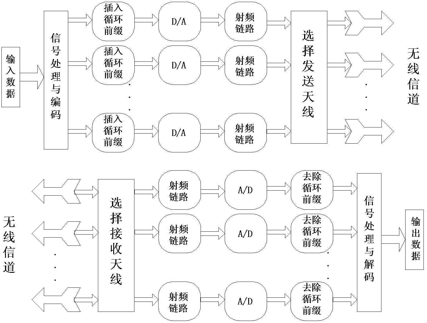
[0037] A MIMO system can obtain performance gains through spatial multiplexing and spatial diversity, but these two methods will increase the hardware cost and complexity of the system. When the system uses multiple transmitting and receiving antennas, the antenna selection technology is used to select the best antenna that matches the transmitting and receiving radio frequency link from multiple transmitting and receiving antennas for receiving or transmitting, so that each radio frequency link of the multi-antenna system can work at Optimal state, thus enabling the MIMO system to obtain the maximum channel capacity while reducing system cost and complexity while retaining the superior performance of the MIMO system.

[0038] However, the MIMO system require...


PUM


Abstract

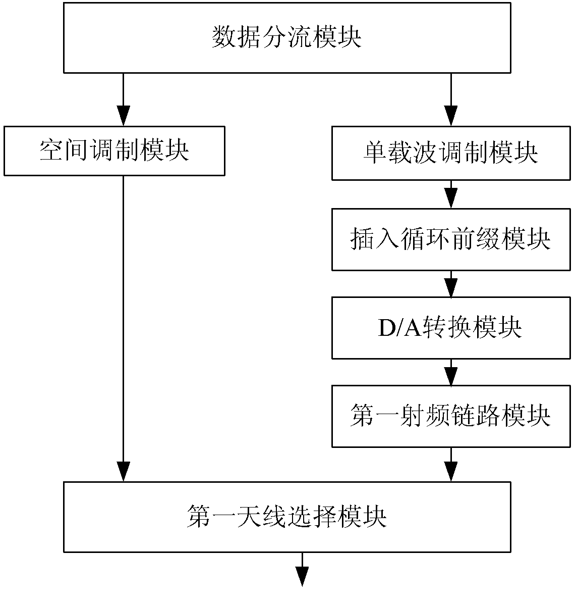
The invention discloses a multi-antenna transmission system and a multi-antenna transmission method. A transmitter of the system comprises a spatial modulation module, a single-carrier modulation module, a cyclic prefix insertion module, a digital/analogue (D/A) conversion module and a first radio frequency link module. The system is characterized in that: the transmitter also comprises a data distribution module and a first antenna selection module. According to the method, an information bit stream to be transmitted is divided into two paths through data distribution, wherein one path comprises information for controlling serial numbers of antennae, and is directly transmitted to an antenna selection module, and the other path comprises data information bits which are modulated, subjected to radio frequency processing and then transmitted to the antenna selection module; and then an antenna is selected to transmit information. Therefore, compared with the conventional method, the method has the advantages that: the number of radio frequency links is decreased; and system cost is decreased.

Description


Claims


Application Information

Patent Timeline
Owner UNIV OF ELECTRONICS SCI & TECH OF CHINA
Learn More