
Equipment cabinet with lifting rings

A technology of lifting rings and cabinets, which is applied in the direction of cabinets/cabinets/drawer parts, etc., which can solve problems such as lifting ring top cover detachment, ring thread wear, and lifting rings falling out, so as to avoid personal accidents, protect cabinets, and have high bearing strength Effect

Inactive Publication Date: 2012-07-18
SUZHOU TANGFENG ELECTRICAL APPLIANCE
View PDF1 Cites 0 Cited by
  • Summary
  • Abstract
  • Description
  • Claims
  • Application Information

AI Technical Summary

Problems solved by technology

However, this installation method makes the load-bearing strength of the lifting ring low. When the weight of the cabinet is large, the lifting ring is easy to come out of the threaded hole, causing the lifting ring to be separated from the top cover of the cabinet. The phenomenon that the cover is detached will cause the cabinet to fall to the ground, causing damage to the cabinet, and even more serious personal accidents
For example, the Chinese invention patent "A Cabinet", the patent number is ZL201020179332.8, discloses a cabinet equipped with suspension rings, the top cover is fixed on the top of the cabinet through the suspension rings, and when the cabinet needs maintenance, the top cover may be opened , which causes the thread of the lifting ring to wear out during frequent use, and it is easier for the lifting ring to separate from the top cover of the cabinet during the lifting process

Method used


Image

  • Equipment cabinet with lifting rings
  • Equipment cabinet with lifting rings
  • Equipment cabinet with lifting rings

Examples


Embodiment Construction

[0014] The present invention is described below in conjunction with accompanying drawing.

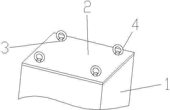
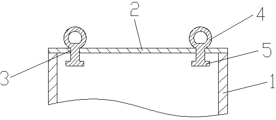
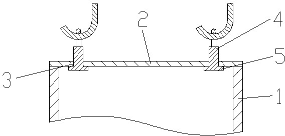
[0015] as attached figure 1 , 2 The shown cabinet with suspension rings in the present invention includes a cabinet body 1 and a top cover 2, and the top cover 2 is provided with mounting holes 3 at four corners; the mounting holes 3 are provided with The suspension ring 4 that can slide up and down along the installation hole 3; the bottom of the suspension ring 4 is provided with a baffle 5; the surface area of ​​the baffle 5 is at least twice the surface area of ​​the installation hole 3. When the cabinet body 1 is not hoisted, the suspension ring 4 slides to the limit position along the installation hole 3, which saves space and avoids unnecessary troubles caused by the staff touching the suspension ring 4 unconsciously.

[0016] as attached image 3 As shown in a cabinet equipped with lifting rings according to the present invention, when the cabinet body 1 is hoisted, the upper...


PUM


Abstract

The invention discloses an equipment cabinet with lifting rings. The equipment cabinet comprises a cabinet body and a top cover, wherein mounting holes are formed in the four corners of the top cover; the lifting rings capable of vertically sliding along the mounting holes are arranged in the mounting holes; a baffle plate is arranged at the bottoms of the lifting rings; and surface area of the baffle plate is at least two times that of the mounting holes and is perfectly 3.5 times that of the mounting holes. According to the equipment cabinet with the lifting rings, the mounting holes are formed in the four corners of the top cover, the lifting rings capable of vertically sliding along the mounting holes are arranged in the mounting holes, and the baffle plate preventing the lifting rings from being separated is arranged at the bottoms of the lifting rings, so that the bearing capacity of the lifting rings is high through the structure, even when the weight of the equipment cabinet is very large, the lifting rings are not easily separated from the top cover of the equipment cabinet when the equipment cabinet is hoisted, the equipment cabinet is effectively protected, and the human injury is further avoided.

Description

technical field [0001] The invention relates to a cabinet equipped with suspension rings, in particular to a cabinet with suspension rings which are not easily separated from the top cover of the cabinet during the lifting process, and belongs to the technical field of electrical equipment shells. Background technique [0002] In the electrical field, the cabinet is a commonly used device on which control electrical components and connecting wires are installed to control the work of related electrical appliances. At present, the top of the cabinet is usually provided with a lifting ring for lifting, so as to facilitate the handling of the cabinet. In the prior art, the top of the cabinet is usually provided with 4 threaded holes, and the lifting rings are usually ring bolts, and the lifting ring bolts are screwed into the threaded holes to realize the installation of the lifting rings. However, this installation method makes the load-bearing strength of the lifting ring lo...

Claims


Application Information

Patent Timeline
IPC IPC(8): H05K5/02
Inventor 唐祥根
Owner SUZHOU TANGFENG ELECTRICAL APPLIANCE
Learn More