Integral Composite Bushing System and Method

a composite bushing and integrated technology, applied in the field of integrated systems and methods for increasing the strength of composite structures, can solve the problems of low out-of-plane sheer resistance of composites, increased drilling holes, and increased cost, weight and manufacturing time of components, so as to achieve effective transfer of load and increase bearing strength

Active Publication Date: 2015-01-29
AURORA FLIGHT SCI CORP
View PDF5 Cites 13 Cited by
  • Summary
  • Abstract
  • Description
  • Claims
  • Application Information

AI Technical Summary

Benefits of technology

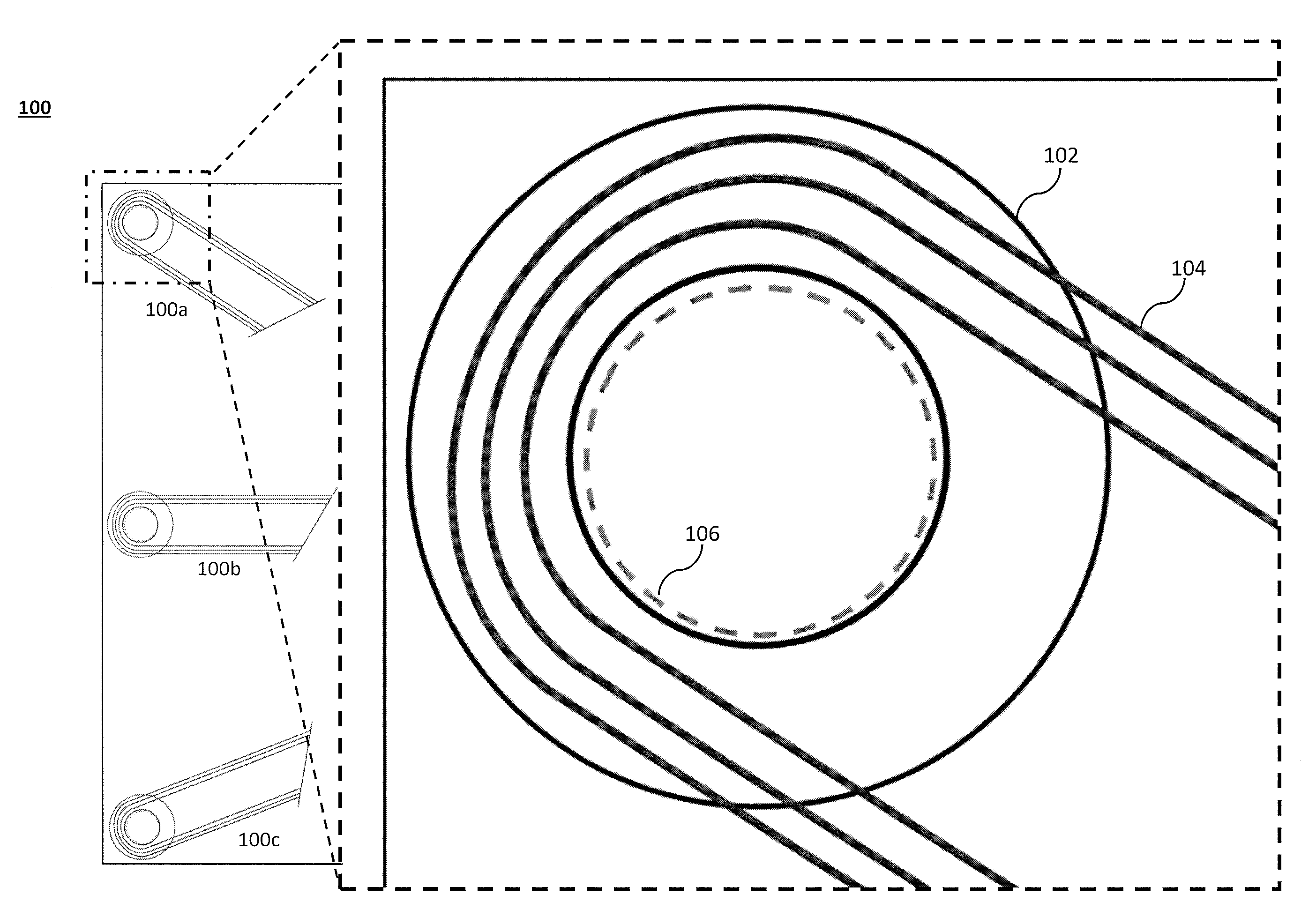
[0009]As set forth below, an integrated composite bearing, which may be added to a composite structure during composite layup, may function as a support structure (or bearing) within the composite structure. This integrated composite bearing, increases the bearing strength as well as more effectively transfer load from the fastener to the panel.

Problems solved by technology

However, composite materials differ from metals in that they have quasi-isentropic properties, which raises two issues in fastening composite structures.
The first issue is in drilling the holes.
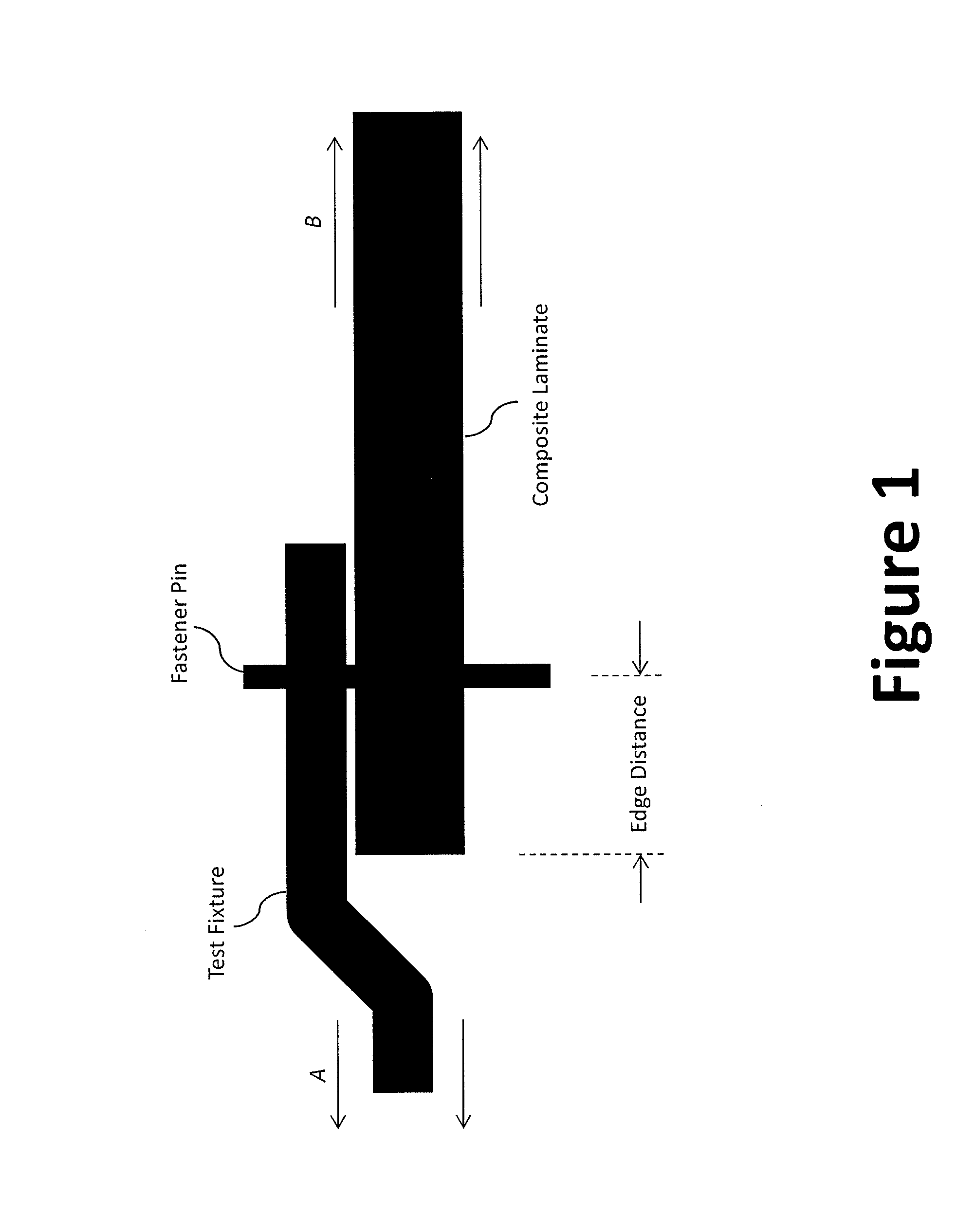
This requires the placement of additional edge material to separate the hole from the edge of the composite structure (e.g., an aircraft component, such as a panel), which increases the cost, weight, and manufacturing time of the component.
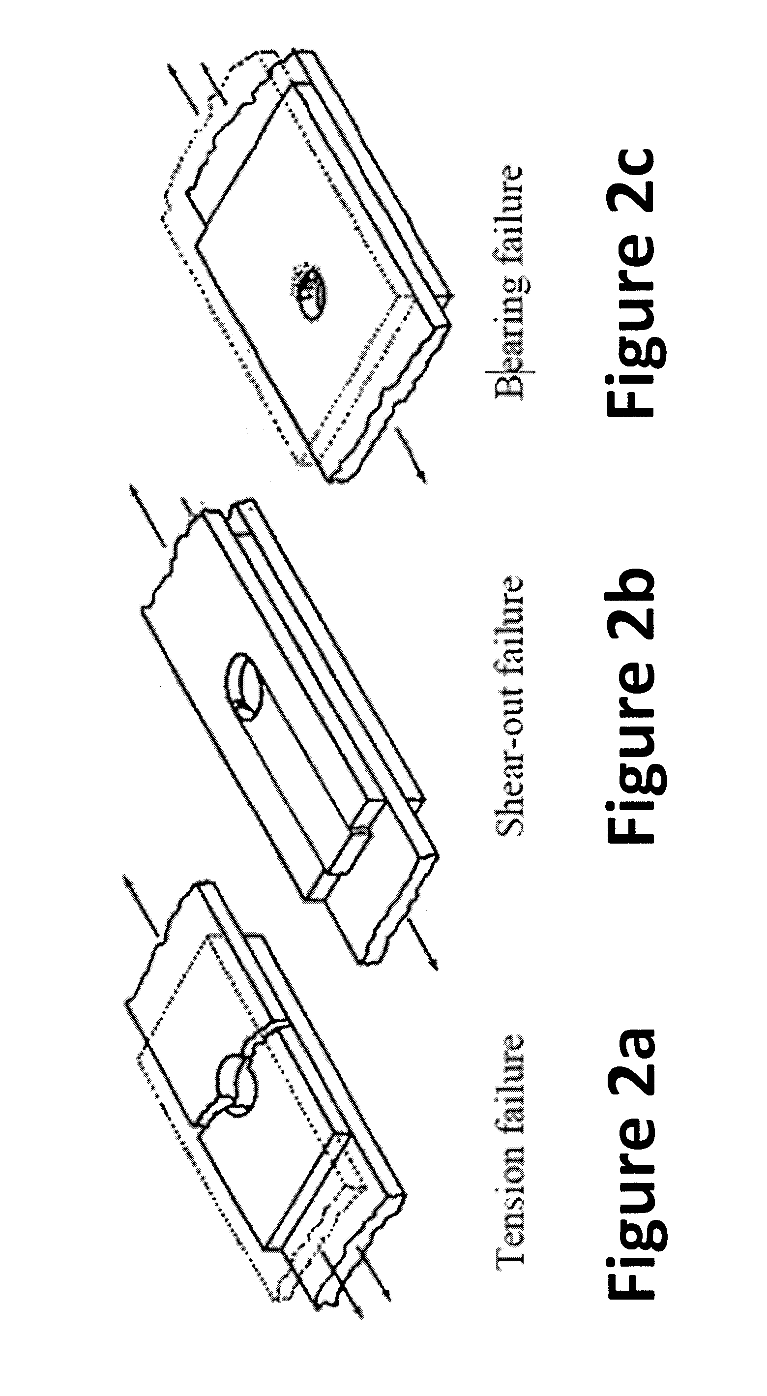
The second issue is due to bearing weakness in the composites.
This is caused by the composite's low out-of-plane sheer resistance.
While a number of composite washers that focus on sealing and conforming to contour have been disclosed, these composite washers do not add any structural benefit to the composite structure.
However, these methods are directed at metal, and would cause delamination if used in a composite structure.
Other methods address ensuring the integrity of the panel during impact, but are not designed for the purpose of transferring load from a fastener.
Yet, other methods for fastener reinforcement involve double-plys, but fail to specify any unique components specifically focused on bearing load or edge distance optimization.
However, such current methods result in an increase in material, and therefore, an increase in weight and cost for each part.

Method used


Image

  • Integral Composite Bushing System and Method
  • Integral Composite Bushing System and Method
  • Integral Composite Bushing System and Method

Examples


Embodiment Construction

[0036]Preferred embodiments of the present invention will be described hereinbelow with reference to the accompanying drawings. In the following description, certain well-known functions or constructions are not described in detail since they would obscure the invention in unnecessary detail. For this application, the following terms and definitions shall apply:

[0037]The term “composite material” as used herein, refers to a material comprising an additive material and a matrix material. For example, a composite material may comprise a fibrous additive material (e.g., fiberglass, glass fiber (“GF”), carbon fiber (“CF”), aramid / para-aramid synthetic fibers, FML, etc.) and a matrix material (e.g., epoxies, polyimides, aluminum, titanium, and alumina, including, without limitation, plastic resin, polyester resin, polycarbonate resin, casting resin, polymer resin, thermoplastic, acrylic resin, chemical resin, and dry resin). Further, composite materials may comprise specific fibers embed...


PUM

PropertyMeasurementUnit
diameteraaaaaaaaaa
diameteraaaaaaaaaa
strengthaaaaaaaaaa

Abstract

A composite bearing comprising a densified portion, wherein a hole location is positioned at the approximate center of said densified portion; and a plurality of filament tendrils, wherein the plurality of filament tendrils are configured to wrap around the hole location to create a “U” shape.

Description

CROSS-REFERENCE TO RELATED APPLICATIONS[0001]This application claims priority to U.S. Provisional Patent Application No. 61 / 858,909, filed on Jul. 26, 2013, entitled “Integral Composite Bearing System And Method,” by Brandon Pollett, which is hereby incorporated by reference in its entirety.TECHNICAL FIELD[0002]The present invention is directed to systems and methods for increasing the strength of a composite structure, specifically, increasing the strength of a fastening point within a composite structure. More specifically, increasing bearing strength and for providing integral composite bearings to resist bearing failure.BACKGROUND[0003]Traditional metal aircraft structures are fastened with rivets, hi-loks fasteners, or equivalent sheer fasteners. However, composite materials differ from metals in that they have quasi-isentropic properties, which raises two issues in fastening composite structures. The first issue is in drilling the holes. Drilling or punching a hole in a compos...

Claims


Application Information

Patent Timeline
Patent Type & Authority Applications(United States)
IPC IPC(8): B64C1/00
CPCB64C2001/0072B64C1/00B29L2031/737B29C70/545B29C70/30B29C70/887Y02T50/40
Inventor POLLETT, BRANDON
Owner AURORA FLIGHT SCI CORP
Why Eureka
Try Eureka