

Helium-recovery plant
A technology for recycling equipment and equipment, applied in lighting and heating equipment, purification/separation of inert gas, liquefaction, etc., can solve problems such as underutilized capacity and infeasibility
- Summary
- Abstract
- Description
- Claims
- Application Information
AI Technical Summary
Problems solved by technology
Method used
Image

Examples
Embodiment Construction
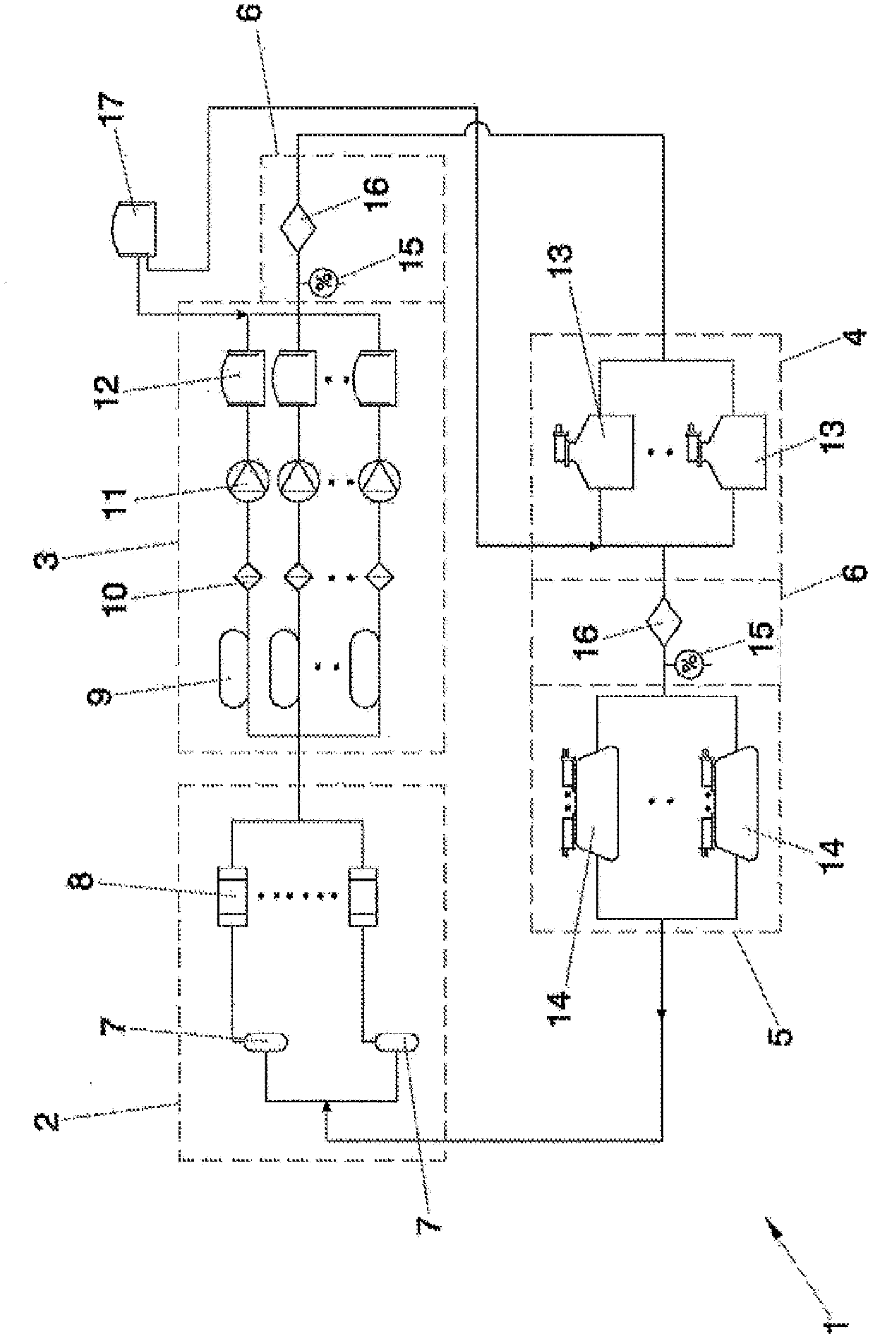
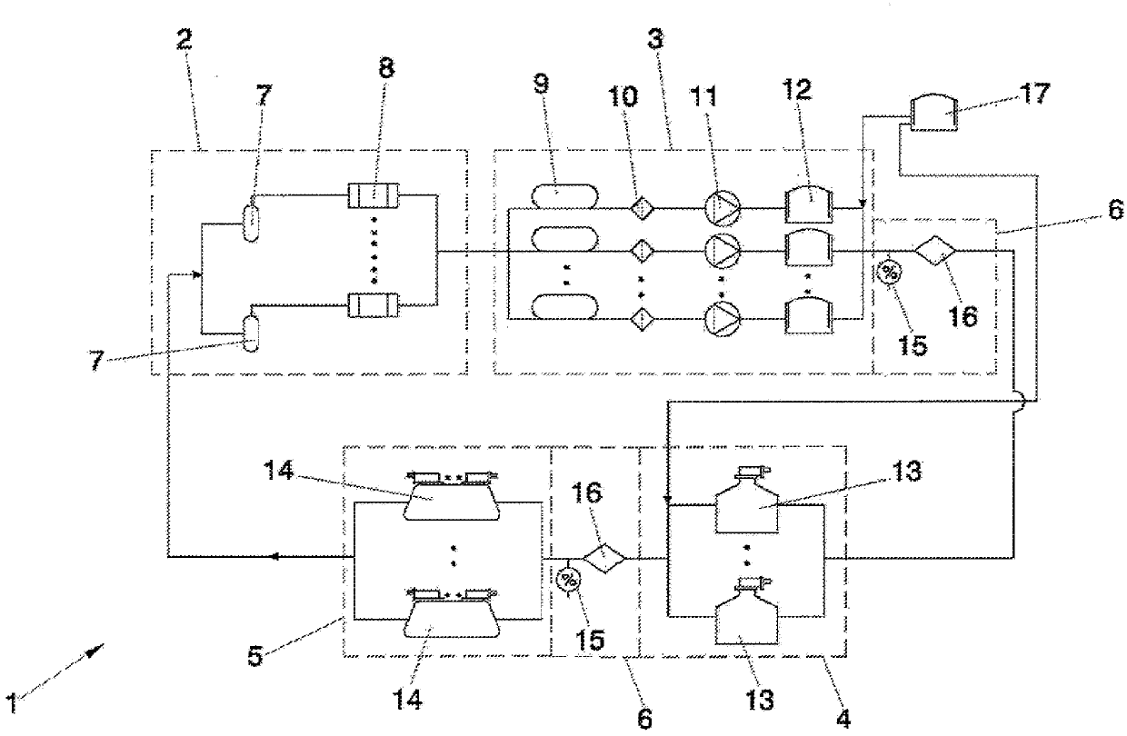
[0027] Such as figure 1 As indicated, a preferred embodiment of the helium recovery plant ( 1 ) object of the present invention is described below.
[0028] Such as figure 1 As shown in , the helium recovery device (1) consists of five modules: recovery module (2), pressurized storage module (3), purification module (4), liquefaction module (5), and distribution module (6) .
[0029]In this recovery module (2), gas is recovered from a series of scientific or medical installations (7) by means of a recovery module (2) ensuring maximum and minimum pressure conditions of the scientific or medical installation (7), such that such installations ( 7) Independently of other modules (3, 4, 5, 6) and ensure lossless recovery. The recovery module (2) includes electronic pressure sensors as well as safety and shut-off valves to evacuate excess helium in case of excessive and unforeseen evaporation in the unit (7).
[0030] Once recovered through the recovery module (2), the helium of...
PUM
 Abstract
Description
Claims
Application Information