Mixing/calcining Furnace

A calcination furnace and calcination technology, applied in furnaces, drum furnaces, furnace types, etc., can solve the problem of unstable gas production and achieve the effect of suppressing calcination loss

Inactive Publication Date: 2012-07-18
MITSUBISHI MATERIALS CORP
View PDF7 Cites 5 Cited by
  • Summary
  • Abstract
  • Description
  • Claims
  • Application Information

AI Technical Summary

Problems solved by technology

As a result there is also CO 2 The problem of unstable gas generation

Method used


Image

  • Mixing/calcining Furnace
  • Mixing/calcining Furnace
  • Mixing/calcining Furnace

Examples


no. 1 approach

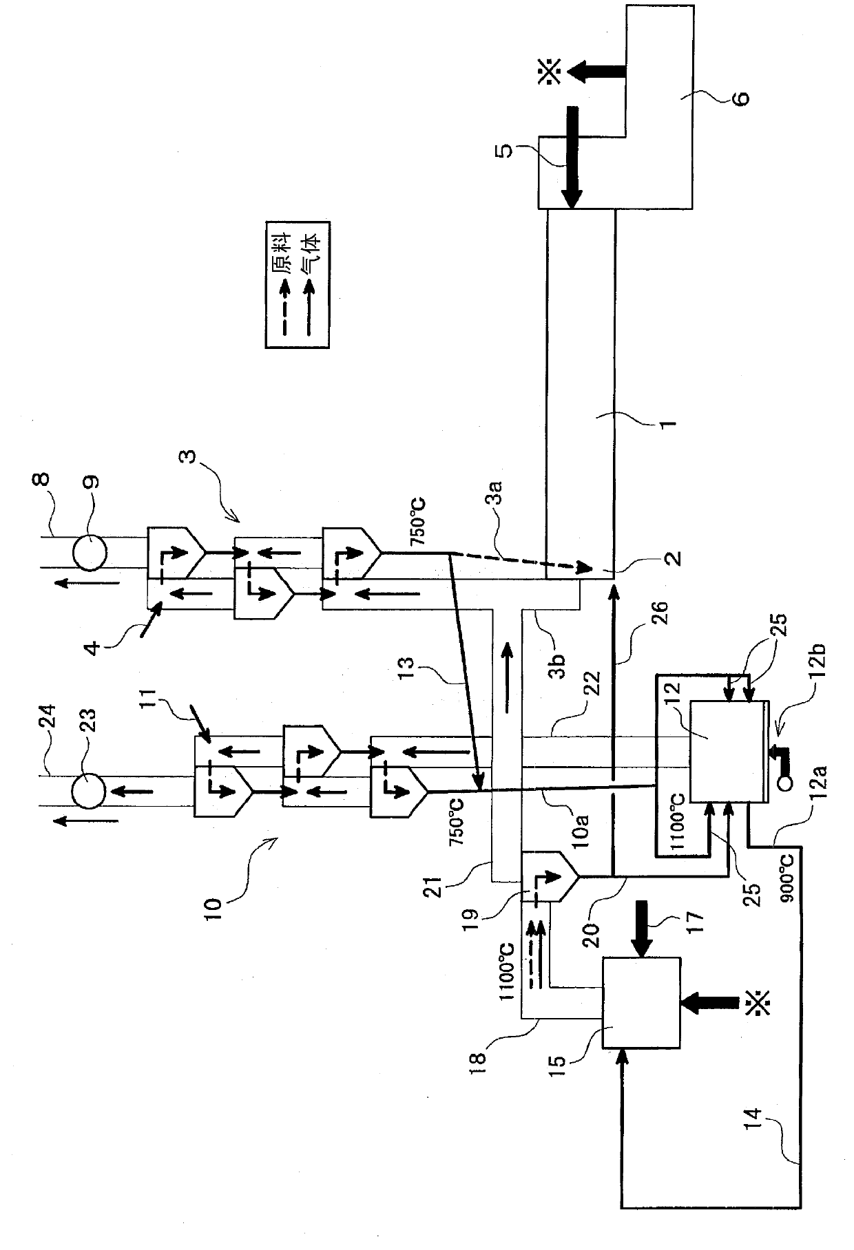
[0109] figure 1 Indicates that the hybrid calciner involved in the present invention is used for CO in cement manufacturing equipment 2 An embodiment of the gas recovery equipment, for the structure of the cement manufacturing equipment, due to the Figure 18 The structures shown are the same, and the description thereof will be simplified by attaching the same symbols.

[0110] exist figure 1 In , the symbol 10 is the second preheater 10 provided independently from the preheater (first preheater) 3 of the cement manufacturing apparatus.

[0111] The second preheater 10, like the above-mentioned first preheater 3, is composed of multi-stage cyclone separators arranged in series in the vertical direction, and the to-be-calcined object (before calcining) is supplied from the supply line 11 to the uppermost cyclone separator. cement raw materials). Furthermore, the bottom of the cyclone separator at the lowest stage of the second preheater 10 is connected to the upper end of...

no. 2 approach

[0148] Figure 9 Represents the CO in the cement manufacturing equipment involved in the present invention 2 An embodiment of the recovery equipment of gas n, for the structure of cement manufacturing equipment, due to the Figure 18 The structures shown are the same, and the description thereof will be simplified by attaching the same symbols.

[0149] exist Figure 9 In , the symbol 110 is the second preheater 110 provided independently from the preheater (first preheater) 3 of the cement manufacturing apparatus.

[0150] The second preheater 110, like the above-mentioned first preheater 3, is constituted by a multi-stage cyclone separator arranged in series in the vertical direction, and the cement raw material before calcining ( Cement raw materials before calcination) k. Furthermore, the bottom of the cyclone separator in the lowermost stage of the second preheater 110 is connected to the upper end of the delivery pipe 110 a , and the lower end of the delivery pipe 110...


PUM

PropertyMeasurementUnit
melting pointaaaaaaaaaa

Abstract

Provided is a mixing / calcining furnace of the fluidized bed-type or spouted bed-type whereby CO2 gas, which is generated in the course of mixing a material to be calcined with a superheat calcined material and calcining the same, can be separated and collected at a high concentration. The mixing / calcining furnace (12), in which a material to be calcined is mixed with a superheat calcined material so as to induce a calcination reaction, is of the fluidized bed-type or spouted bed-type and provided with multiple supply lines (25) for supplying said material to be calcined. Also provided is a mixing / calcining furnace whereby CO2 gas, which is generated in an apparatus for producing cement, can be separated and collected at a high concentration through smooth fluidization or spouting even in the case where the particle diameter of a heat medium is larger than the particle diameter of a cement material.

Description

technical field [0001] The present invention relates to a method for recovering at a high concentration CO generated during calcination by mixing superheated calcined products with calcined products, or mainly generated during calcination of cement raw materials in cement manufacturing facilities 2 Gas mixed calciner. Background technique [0002] In recent years, attempts have been made to reduce carbon dioxide (CO 2 )gas. [0003] The cement industry, together with electricity and steel, is a CO 2 One of the industries that emit the most gas, the CO in the cement industry 2 Gas emission reduction contributes to CO of Japan as a whole 2 The gas emission reduction contributes significantly. [0004] Figure 18 The above-mentioned general cement manufacturing equipment in the cement industry is shown, and reference numeral 1 in the figure is a rotary kiln (cement kiln) for firing cement raw materials. [0005] In the kiln tail part 2 on the left side of the figure of th...

Claims


Application Information

Patent Timeline
Patent Type & Authority Applications(China)
IPC IPC(8): F27B15/02C04B7/44C04B2/10
CPCF27B7/2041C04B7/45B01J8/1818B01J8/1809B01J2208/00646B01J2208/00716F27B15/02C04B2/106Y02P40/18Y02P40/40
Inventor 岛裕和樋口直宽高山佳典小松卓哉王俊柱
Owner MITSUBISHI MATERIALS CORP
Why Eureka
Try Eureka