Computer tomography device

A tomography and computer technology, applied in the field of computer tomography equipment

Inactive Publication Date: 2012-07-18
WENZEL VOLUMETRIK
View PDF5 Cites 2 Cited by
  • Summary
  • Abstract
  • Description
  • Claims
  • Application Information

AI Technical Summary

Problems solved by technology

Furthermore, the technical problem to be solved by the present invention is to prevent adverse damage or degradation of the imaging array of electrons due to intervening ionizing radiation or to minimize adverse effects on the detector electronics

Method used


Image

  • Computer tomography device
  • Computer tomography device
  • Computer tomography device

Examples


no. 1 approach

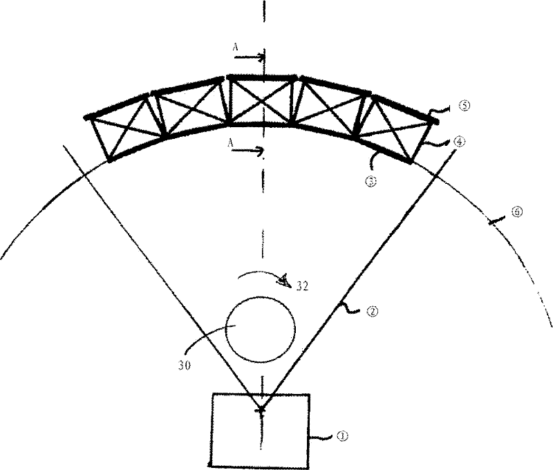
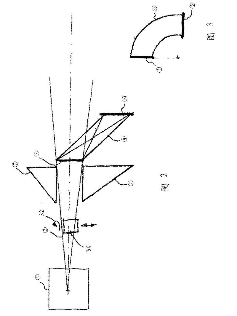
[0024] figure 1 A first embodiment of the invention is shown in a schematic top view: as in figure 1 As can be seen in the top view in , five individual detectors 20 are arranged in the horizontal plane along an arc 6 (radius 2 ), so that within the spread angle 2 with respect to the (assumed point-like) X-ray source 1 A facet shape is formed. The object carrier in the form of a turntable 30 is ideally placed in the radiation path along the line A-A, wherein the x-ray radiation of the source 1 then passes through the object supported thereon and is received by the detector device 20 .

[0025] Accordingly, the turntable has a vertical figure 1 The axis of rotation extending in the plane of view of , so that the direction of rotation is formed along the base arrow (Bodenpfeil) 32 of the turntable corresponding to the arc curvature along the arc 6 .

[0026]Additionally, it is also within the scope of a preferred embodiment of the invention that the turntable 30 is configured...


PUM


Abstract

The invention relates to a computer tomography device for non-medical applications, in particular a non-medical material or workpiece test, having a sensor carrier unit comprising a plurality of individual pixels provided adjacent to one another, said sensor carrier unit being designed to detect invasive radiation of an x-ray radiation source by means of a detector surface.; According to the invention the detector surface extends in at least one plane in the shape of an arc, wherein the sensor carrier unit has a contour that is arced at least in sections and / or comprises a plurality of individual detector elements (20) arranged in a faceted shape, each comprising a flat detector surface (3), disposed adjacent to and / or adjoining one another along an arced line (6), and an object carrier, designed as a rotary plate (30), for a workpiece to be subjected to tomographic inspection is provided in a beam path between the x-ray radiation source (1) and the sensor carrier unit.

Description

technical field [0001] The invention relates to a computed tomography apparatus according to the preamble of the main claim. Background technique [0002] In addition to the field of medical tomography, X-ray tomography is now also established for examining workpieces or materials, in which, similar to human medical or veterinary computed tomography, the workpiece is acted upon by means of high-power X-rays as interventional radiation and transmission. In this case, the workpiece as measurement object is located between a (high-power) x-ray source and an electronic x-ray detector, which converts the received radiation signals into an electrically estimable signal and then uses the Furthermore, known digital imaging methods form the desired image from this signal, including an image of a possible defect, an image of a cavity in a workpiece, etc. [0003] In addition to the formation of the x-ray source, in particular the realization of the x-ray detector is crucial for the ...

Claims


Application Information

Patent Timeline
IPC IPC(8): G01T1/29G01N23/04
CPCG01T1/2985G01N23/046G01N2223/419G01N2223/612
Inventor M.西蒙
Owner WENZEL VOLUMETRIK
Why Eureka
Try Eureka