Switch device operating mechanism

A switch device and operating mechanism technology, applied in the direction of contact operating mechanism, electric switch, high-voltage/high-current switch, etc., can solve the problems of easy disengagement of the latch, failure to maintain the closed state, troublesome position adjustment, etc., and achieve easy position Effects of adjustment, high reliability, and load reduction

Active Publication Date: 2015-01-14
MITSUBISHI ELECTRIC CORP
View PDF4 Cites 0 Cited by
  • Summary
  • Abstract
  • Description
  • Claims
  • Application Information

AI Technical Summary

Problems solved by technology

At this time, since the distance from the engaging part to the rotation center position of the trip latch is large, there is a problem that the latch is easy to disengage when the direction of the force line is shifted, the position adjustment is troublesome, and the closing position may not be correct in some cases. status hold

Method used


Image

  • Switch device operating mechanism
  • Switch device operating mechanism
  • Switch device operating mechanism

Examples


Embodiment approach 1

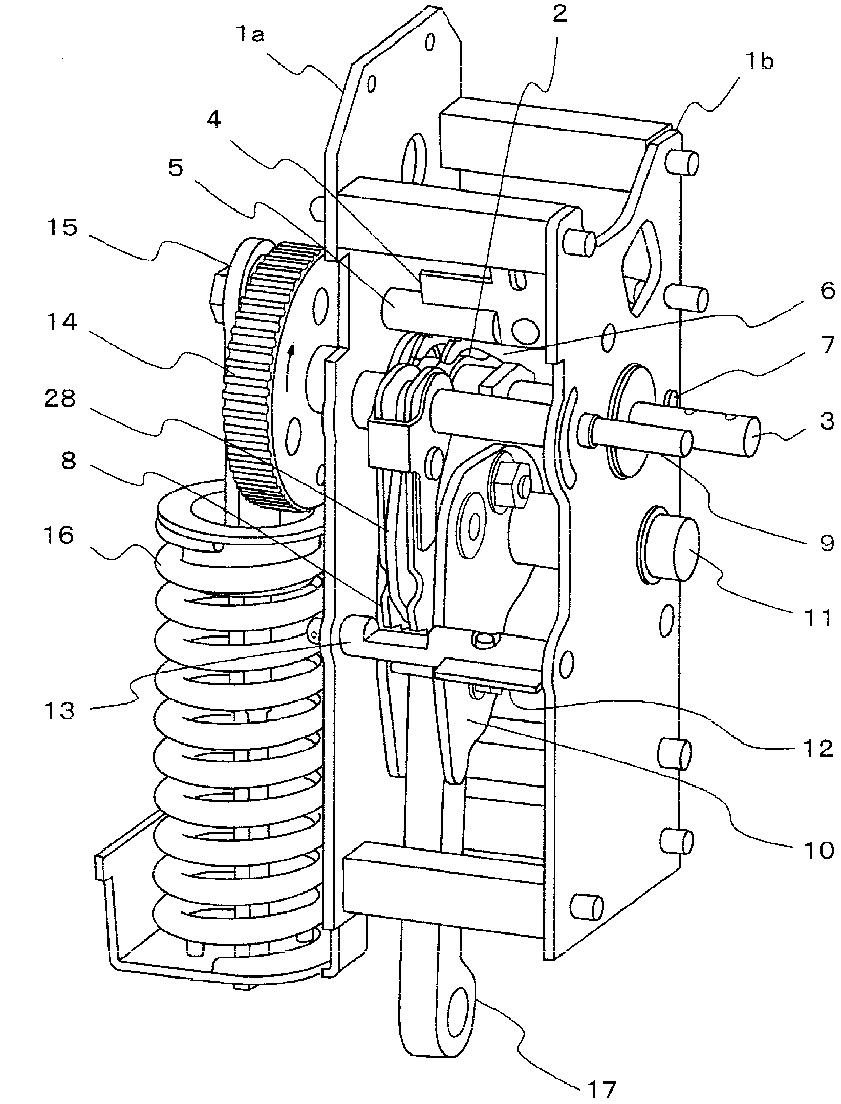
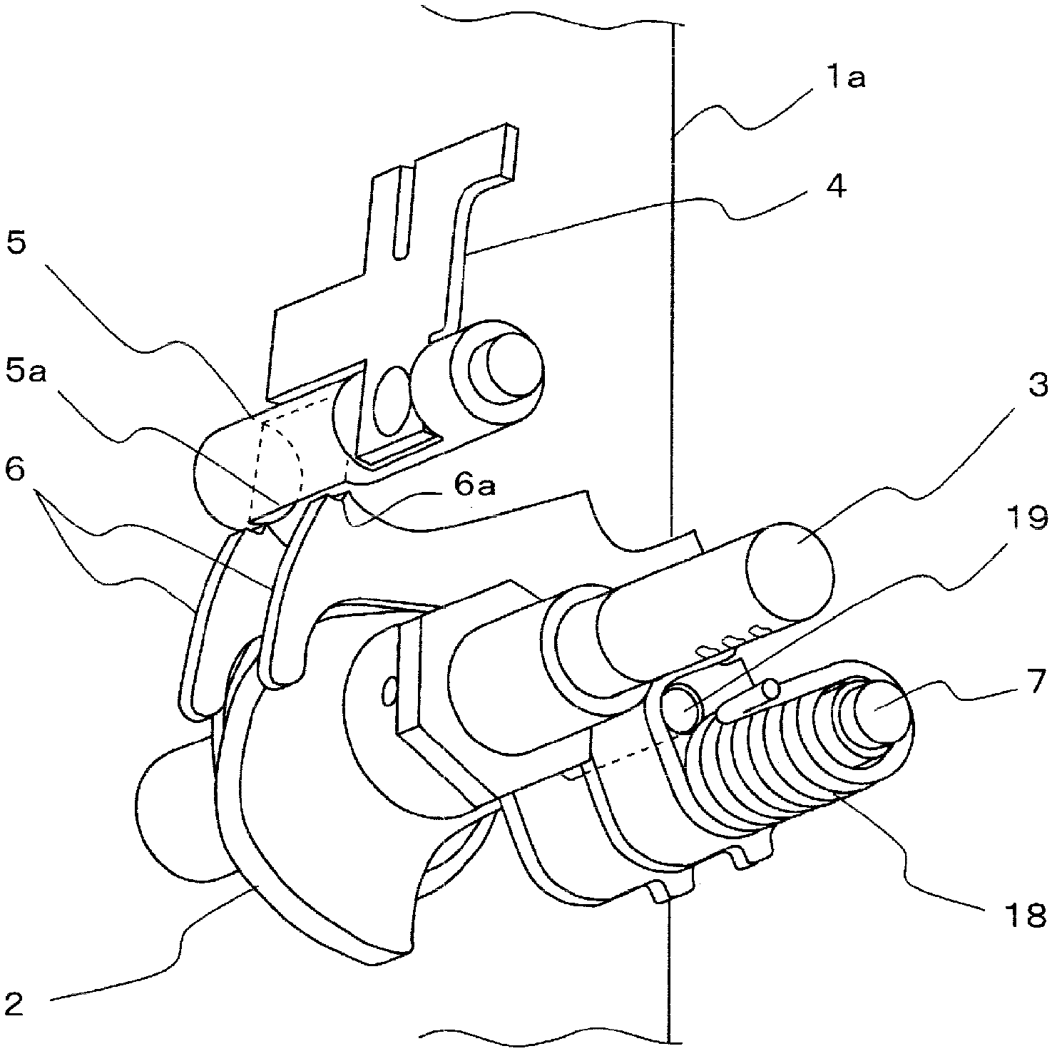
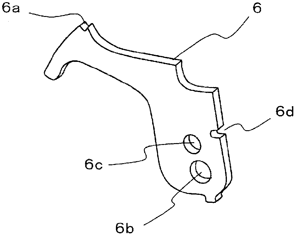
[0027] figure 1 It is a perspective view of the operating mechanism of the switchgear of Embodiment 1. As a switching device, for example, a vacuum circuit breaker using a vacuum valve will be described as an example. First, use figure 1 The perspective view of the figure illustrates the overall structure of the operating mechanism. However, in figure 1 There are also parts that are hidden inside and whose shape is not easy to understand, so, figure 1 It is mainly to explain the arrangement relationship between each component, and for the details of the shape of each part, we will use Figure 2 ~ Figure 6 The partial diagram is described.

[0028] Such as figure 1 As shown, a camshaft 3 is disposed between two frames 1a and 1b having different shapes, and the camshaft 3 is fixedly connected with a cam 2 for transmitting a closing driving force. A first half-moon latch 5 is arranged above the camshaft 3, and a closing lever shaft 7 is arranged behind the camshaft 3, wher...


PUM


Abstract

Included are: a closing spring which provides a closing drive force for closing a contact of a switch device by rotating a camshaft by release of energy; a first semi-circular latch which retains stored energy of the closing spring via a closing lever; an output lever which pivots by being pressed by a cam provided on the camshaft when retention by the first semi-circular latch is released and the energy of the closing spring is released, and transmits the closing drive force to the switch device via a linking mechanism; and a second semi-circular latch which prevents the output lever from pivoting in a tripping direction via a tripping lever and retains stored energy of an interrupting spring provided on the linking mechanism, the pivoting of the output lever being caused by transmission of the stored energy of the interrupting spring.

Description

technical field [0001] The invention relates to an operating mechanism of switch devices such as circuit breakers and switches. Background technique [0002] As conventional operating mechanisms used in switchgears such as circuit breakers, for example, the following technologies are disclosed. [0003] The operating mechanism has a cut-off spring for open-circuit action by releasing stored force and a closing spring for closed-circuit action by releasing stored force, the stored energy of the stop spring is released by releasing hold of the stored energy of the stop spring under the action of a trip trigger To carry out the open-circuit action, by releasing the energy storage of the closing spring under the action of the closing trigger, the energy storage is released to perform the closed-circuit action. The trip trigger and the close trigger are independently and rotatably mounted on the same trigger shaft. In the closed state, the load after the force of the cut-off spr...

Claims


Application Information

Patent Timeline
Patent Type & Authority Patents(China)
IPC IPC(8): H01H33/42H01H33/40
CPCH01H3/3031H01H33/40H01H33/42
Inventor 山本洋平十鸟洋山中丈明
Owner MITSUBISHI ELECTRIC CORP
Why Eureka
Try Eureka