Orthodontic measuring device based on force and torque sensor

A torque sensor and measuring device technology, applied in the field of orthodontics, can solve problems such as poor measurement accuracy, difficulty in mastering by orthodontists, and high cost, and achieve the effects of easy disassembly and assembly, cleaning, disinfection and maintenance

Inactive Publication Date: 2012-07-25
LANZHOU UNIVERSITY
View PDF6 Cites 11 Cited by
  • Summary
  • Abstract
  • Description
  • Claims
  • Application Information

AI Technical Summary

Problems solved by technology

For in vitro measurement, the operator needs to bind the arch wire and brackets on the dental model before measurement, which is a complicated operation; for severe malocclusion, it cannot be measured; at the same time, in vitro measurement requires indirect measurement with the help of measuring tools such as calipers Orthodontic force, so the measurement accuracy is poor and the error is large
In foreign countries, industrial measuring robots with multiple degrees of freedom are used to measure the orthodontic force of arch wire deformation through force sensors. Due to the use of fully automatic control of the mechanical arm, the cost is very expensive.
There are also reports from abroad that the stress sensor is integrated into the sensitive bracket, but the cost of making a dental model is high for each measurement, and only one dental model can be measured at a time, so the procedure is complicated
In addition, this method needs the help of a computer to convert the stress value into the corresponding force value through data processing, which is not easy for orthodontists to master.

Method used


Image

  • Orthodontic measuring device based on force and torque sensor
  • Orthodontic measuring device based on force and torque sensor
  • Orthodontic measuring device based on force and torque sensor

Examples


Embodiment Construction

[0021] The preferred embodiments of the present invention will be described below in conjunction with the accompanying drawings. It should be understood that the preferred embodiments described here are only used to illustrate and explain the present invention, and are not intended to limit the present invention.

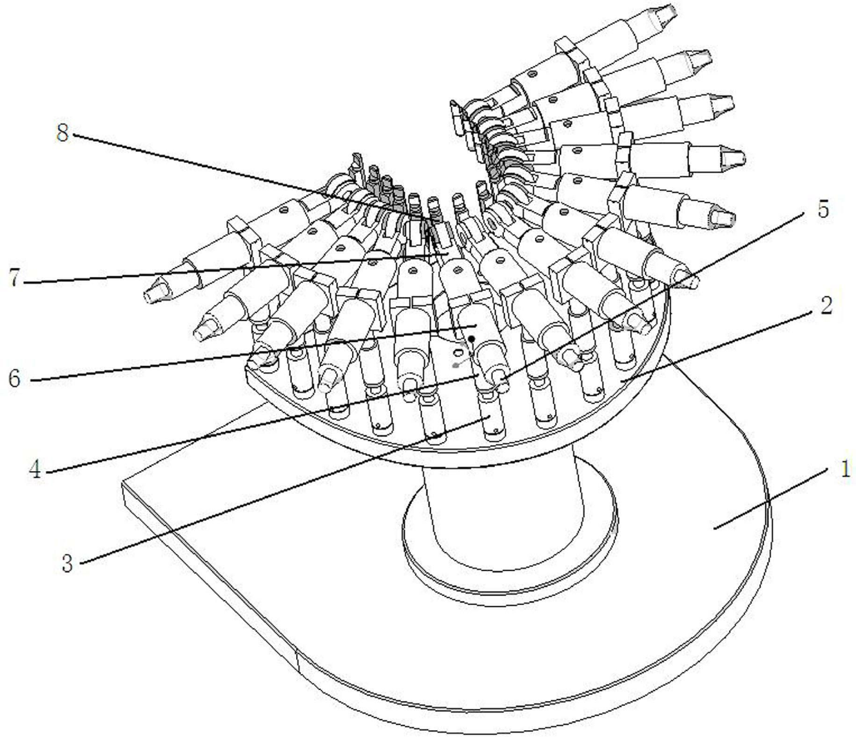
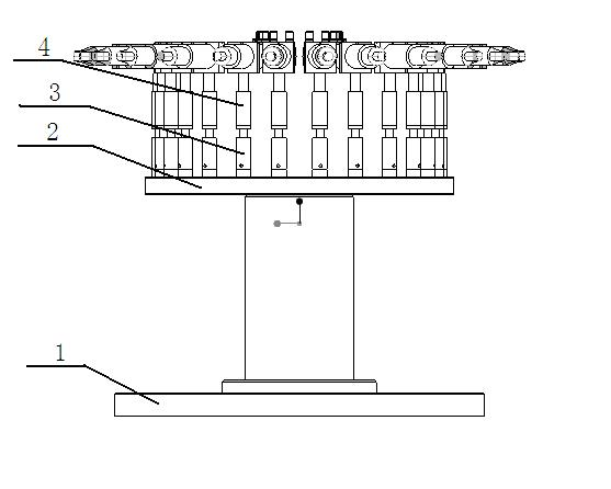
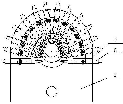
[0022] Such as Figure 1-8 As shown, it includes a support base 1, a fixed chassis platform 2 and main measuring components. The support base 1 is fixedly connected with a fixed chassis platform 2 by bolts. The support base 1 is horseshoe-shaped, and a connecting column is fixedly installed in the center. The fixed chassis platform 2 is fan-shaped, and fourteen fixed columns are fixedly installed on the front end arc edge of the fixed chassis platform 2, and the fixed columns coincide with the distribution positions of the teeth. The main measuring parts include vertical shaft sleeve 3, clamping ring 4, horizontal feed shaft 5, horizontal shaft sleeve 6, YOZ plane r...


PUM


Abstract

The invention provides an orthodontic measuring device based on a force and torque sensor. The orthodontic measuring device comprises a supporting base, a chassis fixing platform and a main body measuring component, wherein the supporting base is fixedly connected to the chassis fixing platform, and fourteen fixing columns are arranged at the arc edges of the front end of the chassis fixing platform; the main body measuring component comprises an upright shaft sleeve, a clamping ring, a horizontal shaft sleeve, a horizontal feeding shaft, a YOZ plane rotating shaft, a XOZ plane adjusting component and a XOY plane fine adjusting component, wherein the upright shaft sleeve is sleeved on a fixing column and fixedly connected with the clamping ring; the horizontal shaft sleeve is clamped at the upper part of the clamping ring, with two ends sleeved with the horizontal feeding shaft and the YOZ plane rotating shaft, respectively; the YOZ plane rotating shaft is movably connected with the XOZ plane adjusting component, and the XOZ plane adjusting component is sleeved with the XOY plane fine adjusting component; a micro sensor is arranged into the XOY plane fine adjusting component; the main body measuring component is connected by a flat end fastening bolt. By using the orthodontic measuring device provided by the invention, the dentition in the oral can be precisely positioned so as to achieve orthodontic correction force and torque measuring.

Description

technical field [0001] The invention belongs to the technical field of orthodontics, in particular to a measuring device for orthodontic correction force. Background technique [0002] In the process of orthodontic treatment, the orthodontic force is realized by deforming the archwire to generate restoring force due to the configuration difference between the predetermined shape of the archwire and the actual arrangement shape of the teeth. The movement of the teeth is realized due to the orthodontic force and its torque to the impedance center. Therefore, the study of the initial stage of orthodontic treatment and the force and torque exerted by the arch wire on the teeth during the treatment process has a great impact on orthodontic theory and clinical practice. Treatment is of great importance. [0003] At present, domestic orthodontic force measuring devices are divided into internal measuring devices and external measuring devices. For severely misaligned teeth, the i...

Claims


Application Information

Patent Timeline
Patent Type & Authority Applications(China)
IPC IPC(8): A61C19/04
Inventor 陈宏伟安晓莉周又和王记增
Owner LANZHOU UNIVERSITY
Why Eureka
Try Eureka