Bag type dust-collecting built-in bag cage and combined mounting structure of bag cage and filtering bag on tube sheet

A bag-type dust removal and built-in technology, which is applied in the direction of dispersed particle filtration, dispersed particle separation, chemical instruments and methods, etc., can solve problems such as troublesome installation and operation, and achieve the effect of convenient installation and operation and saving height

Active Publication Date: 2015-01-21
科林环保技术有限责任公司
View PDF4 Cites 0 Cited by
  • Summary
  • Abstract
  • Description
  • Claims
  • Application Information

AI Technical Summary

Problems solved by technology

[0002] The existing bag cage includes multiple vertical ribs arranged at intervals in the circumferential direction, horizontal ribs connected between the multiple vertical ribs, and the tops of the multiple vertical ribs are Fixed on the lower connecting pipe, the bag cage is inserted in the filter bag, and the vertical ribs are used to support the opening of the filter bag. The outer peripheral surface of the filter bag is close to the bag mouth, and the outer peripheral surface of the lower connecting pipe has extending along the circumferential direction. The ring-shaped groove, the groove of the filter bag, and the groove of the lower connecting pipe are in good correspondence, and then the filter bag is tightly placed on the lower connecting pipe through the hoop, and the lower connecting pipe can separately cover the lower part of the upper connecting pipe, and the upper connecting pipe The upper part has a circumferential flange, which is fastened on the edge of the flower plate hole, and then the circumferential flange of the upper connecting pipe is fixed on the flower plate by screws, so that the bag cage is installed on the flower plate and the When the filter bag is used, the installer must climb above the flower plate to install the upper nozzle, that is, to complete the installation of the bag cage, which is troublesome to install

Method used


Image

  • Bag type dust-collecting built-in bag cage and combined mounting structure of bag cage and filtering bag on tube sheet
  • Bag type dust-collecting built-in bag cage and combined mounting structure of bag cage and filtering bag on tube sheet
  • Bag type dust-collecting built-in bag cage and combined mounting structure of bag cage and filtering bag on tube sheet

Examples


Embodiment Construction

[0018] The structure of the present invention will be further described below in conjunction with the accompanying drawings.

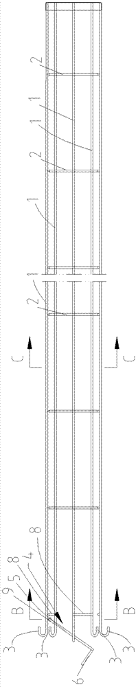
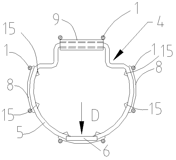
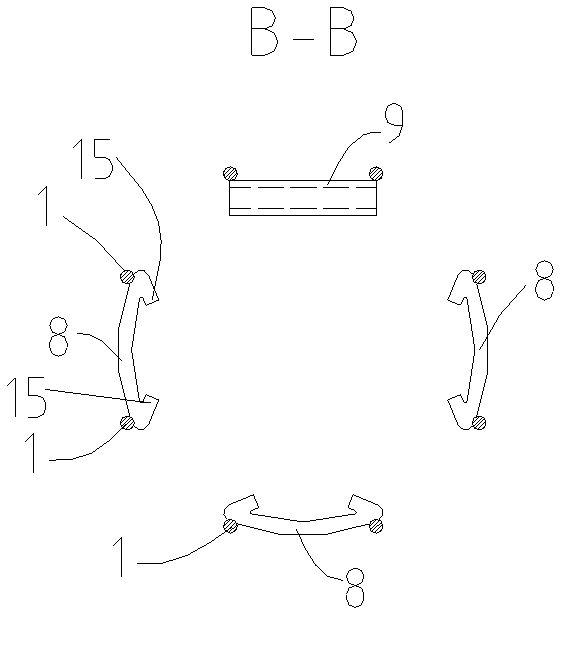
[0019] exist Figure 1-6 Among them, a built-in bag cage, including a plurality of vertical ribs 1 arranged at intervals along the circumferential direction, and transverse ribs 2 connected between the lower parts of the plurality of vertical ribs 1, and the positions where the plurality of vertical ribs 1 are located above the transverse ribs 2 can be Elastically deformable, in this embodiment, the vertical ribs 1 are made of metal material, so they can be elastically deformed, the multiple vertical ribs 1 surround the frame of the bag cage, and the horizontal ribs 2 ensure the stability between the lower parts of the multiple vertical ribs 1 Positioning, the tops of the multiple vertical ribs 1 are all bent outwards to form a hook 3, and the upper ends of the multiple vertical ribs 1 are provided with a stretching structure 4 that can expand the ...


PUM


Abstract

The invention discloses a bag type dust-collecting built-in bag cage and a combined mounting structure of the bag cage and a filtering bag on a tube sheet. The bag cage in inserted into the filtering bag, and when the bag cage is mounted into a hole of the tube sheet a mounting worker forcedly folds the upper ends of vertical ribs and the upper end of the filtering bag, so that the upper ends of the bag cage and the filtering bag can pass through the tube sheet hole; the vertical ribs are released and hands are stretched into the adjacent hole of the tube sheet to operate an expanding structure, so that a plurality of the vertical ribs are stably expanded; lifting hooks at the top ends of the plurality of the vertical ribs stretch out of the opening of the filtering bag to be hooked on the upper surface at the periphery of the hole of the tube sheet; and meanwhile, the opening of the filtering bag is tightly held by elastic acting force of an elastic piston ring, so that the hole edge of the tube sheet hole is inserted into a groove of the opening of the filtering bag; and therefore, the filtering bag is stably positioned. When mouting the bag cage and the filtering bag, the mounting worker only needs to stand below the tube sheet to operate the expanding structure from the adjacent tube sheet hole to finish the mounting without need of climbing on the tube sheet, so that the mounting operation is convenient and the height of a space above the tube sheet is saved.

Description

Technical field [0001] The present invention involves a bag dust removal internal bag cage, and also involves the combined installation structure of the bag cage and filter bag on the flower plate. Background technique [0002] The existing bag cages, including the vertical tendons arranged by multiple roots along the distance, the horizontal tendons connected between the multiple vertical tendons, the top of the multiple vertical tendons is fixed on the bottom pipe.The tendon supports the effect of opening the filter bag. The outer surface of the filter bag is near the position near the mouth of the bag and the outer perimeter that is taken over by the outside.The position of the groove corresponds, and then the filter bag is tightly connected to the lower pipe through the hug.On the edge of the holes of the flower plate, the Zhou Xiang's edge is fixed on the flower plate through the screw, so that when installing a bag and filter bag on the flower plate, the installer must clim...

Claims


Application Information

Patent Timeline
Patent Type & Authority Patents(China)
IPC IPC(8): B01D46/06
Inventor 汤建珍
Owner 科林环保技术有限责任公司
Why Eureka
Try Eureka