
Environment monitoring device

A technology of environmental monitoring and installation frame, which is applied in environment-related fields, and can solve the problems of reducing sampling efficiency, reducing soil monitoring work efficiency, and manpower consumption

Pending Publication Date: 2021-02-12
XUZHOU JIANGMEI TECH
View PDF9 Cites 0 Cited by
  • Summary
  • Abstract
  • Description
  • Claims
  • Application Information

AI Technical Summary

Problems solved by technology

[0003] Soil monitoring in the existing environmental monitoring cannot be stably positioned when soil sampling is performed, and manual assistance is required to maintain the stability of the overall device, which consumes manpower and reduces sampling efficiency, thereby reducing the efficiency of soil monitoring.

Method used


Image

  • Environment monitoring device
  • Environment monitoring device
  • Environment monitoring device

Examples


Embodiment 1

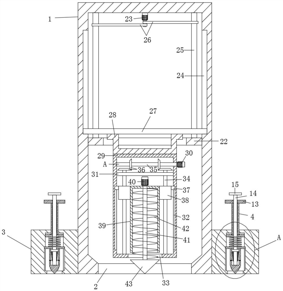
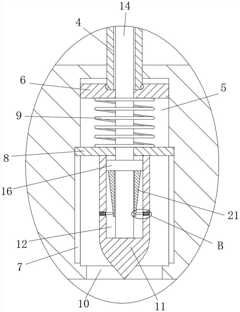
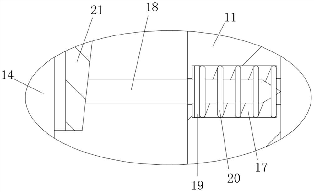
[0022] see Figure 1-3 , an environmental monitoring device, including a monitoring installation frame 1, a sampling assembly, and an adjustment assembly that drives the sampling assembly to move vertically. The bottom of the monitoring installation frame 1 is provided with an avoidance groove 2. Inside; the outside of the monitoring installation frame 1 is symmetrically provided with a positioning assembly, and the positioning assembly includes a positioning seat 3 fixedly installed under the outer wall of the monitoring installation frame 1 and a positioning drive rod 4 threaded on the positioning seat 3, so that The interior of the positioning drive rod 4 is hollowed out, and the upper end of the positioning drive rod 4 is fixedly equipped with a hollow handle 13. The positioning seat 3 located below the positioning drive rod 4 is provided with a polygonal blind groove 5, and the polygonal blind groove 5 is located below the positioning drive rod 4. The bottom of the positi...

Embodiment 2

[0032] This embodiment is further improved on the basis of the embodiment, and the improvement is that: the bottom inner wall of the monitoring installation frame 1 is a "V"-shaped surface; by setting the bottom inner wall of the monitoring installation frame 1 as a "V"-shaped surface, thereby Avoid sampling soil accumulation in the monitoring installation frame 1 when taking out the sampling soil.

[0033] The working principle of this embodiment is: by setting the bottom inner wall of the monitoring installation frame 1 as a "V" shape, it is possible to prevent the sampled soil from accumulating in the monitoring installation frame 1 when taking out the sampling soil.


PUM


Abstract

The invention discloses an environment monitoring device which comprises a monitoring mounting frame, a sampling assembly and an adjusting assembly; positioning assemblies are symmetrically arranged on the outer side of the monitoring mounting frame, each positioning assembly comprises a positioning seat and a positioning driving rod connected to the positioning seat in a threaded mode, and a polygonal blind groove is formed in each positioning seat; a polygonal driving plate matched with the polygonal blind groove is rotationally installed at the end of the positioning driving rod, and secondary positioning assemblies are symmetrically arranged at the bottom of the polygonal limiting plate; Each secondary positioning assembly comprises a right trapezoid seat and a secondary positioning rod; by arranging the positioning driving rod, the positioning column, the lead screw, the right trapezoid seats and the secondary positioning rods, under the combined action of the positioning column and the secondary positioning rods, stable positioning of the whole device is achieved, manual auxiliary supporting is not needed, and the stability of the whole device is kept; labor is not consumed,and meanwhile, workers can concentrate on soil sampling conveniently.

Description

technical field [0001] The present invention relates to the environment-related field, in particular to an environment monitoring device. Background technique [0002] Environmental monitoring is classified according to the monitoring medium or object, and can be divided into water quality monitoring, air monitoring, soil monitoring, solid waste monitoring, biological monitoring, noise and vibration monitoring, electromagnetic radiation monitoring, radioactivity monitoring, thermal monitoring, light monitoring, sanitation monitoring, etc. [0003] Soil monitoring in the existing environmental monitoring cannot be stably positioned when soil sampling is performed, and manual assistance is required to maintain the stability of the overall device, which consumes manpower and reduces sampling efficiency, thereby reducing the efficiency of soil monitoring. Contents of the invention [0004] The object of the present invention is to provide an environment monitoring device to so...

Claims


Application Information

Patent Timeline
IPC IPC(8): G01N1/08G01D11/00G01D11/30
CPCG01N1/08G01D11/00G01D11/30
Inventor 李臣华李群韩迪张昌伟李高文吴旭旭尹敏敏
Owner XUZHOU JIANGMEI TECH
Learn More