Pressure-variable adsorption gas separation device

A gas separation and pressure swing adsorption technology, which is applied in separation methods, dispersed particle separation, chemical instruments and methods, etc., can solve the problems of increasing the instantaneous adsorption capacity of adsorbents and affecting the effective separation capacity of adsorbents, so as to improve the effective separation The effect of improving capacity, concentration and gas production rate

Inactive Publication Date: 2012-07-25
长兴山立化工材料科技有限公司
View PDF3 Cites 6 Cited by
  • Summary
  • Abstract
  • Description
  • Claims
  • Application Information

AI Technical Summary

Benefits of technology

This patented technology allows for better control over the pressure balance within multiple adsorsion columns during operation compared to previous methods like liquid pump systems or solid phase separators (SPS). It also enhances efficient removal of impurities such as nitrogen oxides while maintaining good performance at lower temperatures. Overall, this new design results in more pure products being produced than previously possible due to reduced energy consumption and cost savings associated therewith.

Problems solved by technology

This patented describes a method for separating gases based upon their affinity properties. By applying pressure differences across multiple columns filled with specific types of materials like activated carbon, zirconia, silica gel, alumina, ceramic, etc., each column becomes selective towards one type of gas while others stay behind other ones. These techniques improve efficiency when collecting separated products compared to traditional processes where all components were removed together beforehand.

Method used


Image

  • Pressure-variable adsorption gas separation device
  • Pressure-variable adsorption gas separation device
  • Pressure-variable adsorption gas separation device

Examples


Embodiment 1

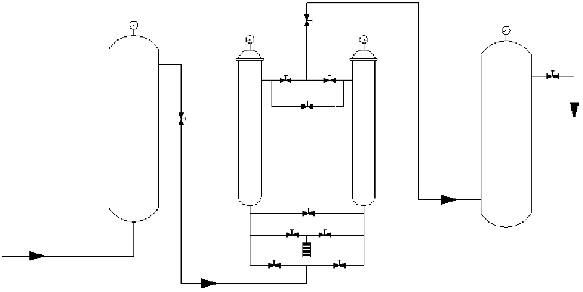
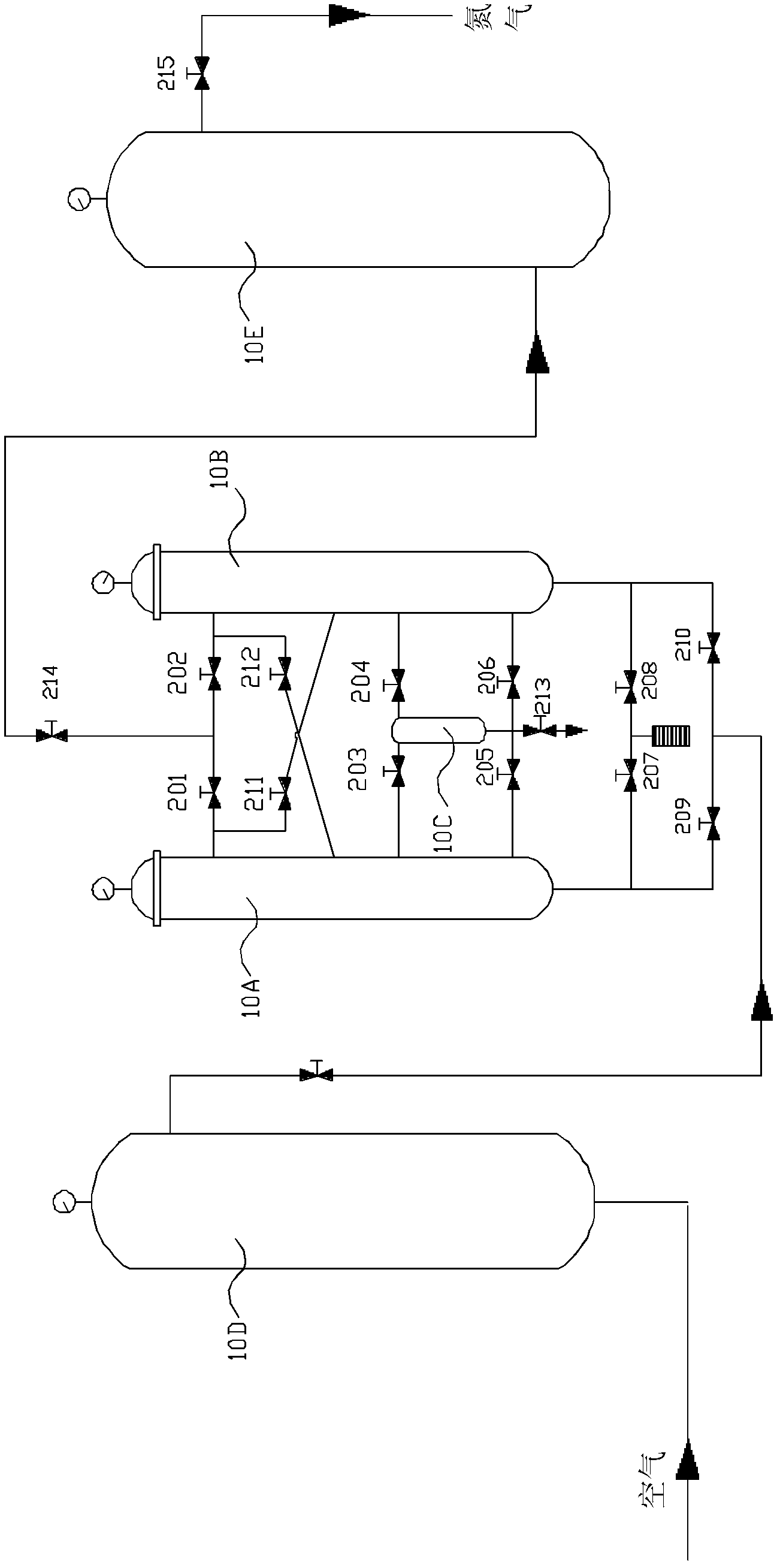
[0042] see image 3 , a pressure swing adsorption gas separation device, comprising two adsorption towers 10A and 10B, and a compressed air storage tank 10D and a nitrogen product gas storage tank 10E, an adsorption sub-tower 10C (adsorption sub-tower 10C) is arranged between the two adsorption towers Volume is 5% of adsorption tower volume), described adsorption auxiliary tower 10C is connected with adsorption tower 10A and 10B by pipeline and valve 203,204,205,206, is filled with molecular sieve adsorbent in the adsorption auxiliary tower 10C, two adsorption towers The top of the tower and the top of the tower, the bottom of the tower and the bottom of the tower are respectively connected by pipelines and valves (that is, the tops of the adsorption towers 10A and 10B are connected by pipelines and valves 201, 202, and the bottoms of the adsorption towers 10A and 10B are connected by pipelines and valves 207 , 208 are connected), the tower top of adsorption tower 10A is conne...

Embodiment 2

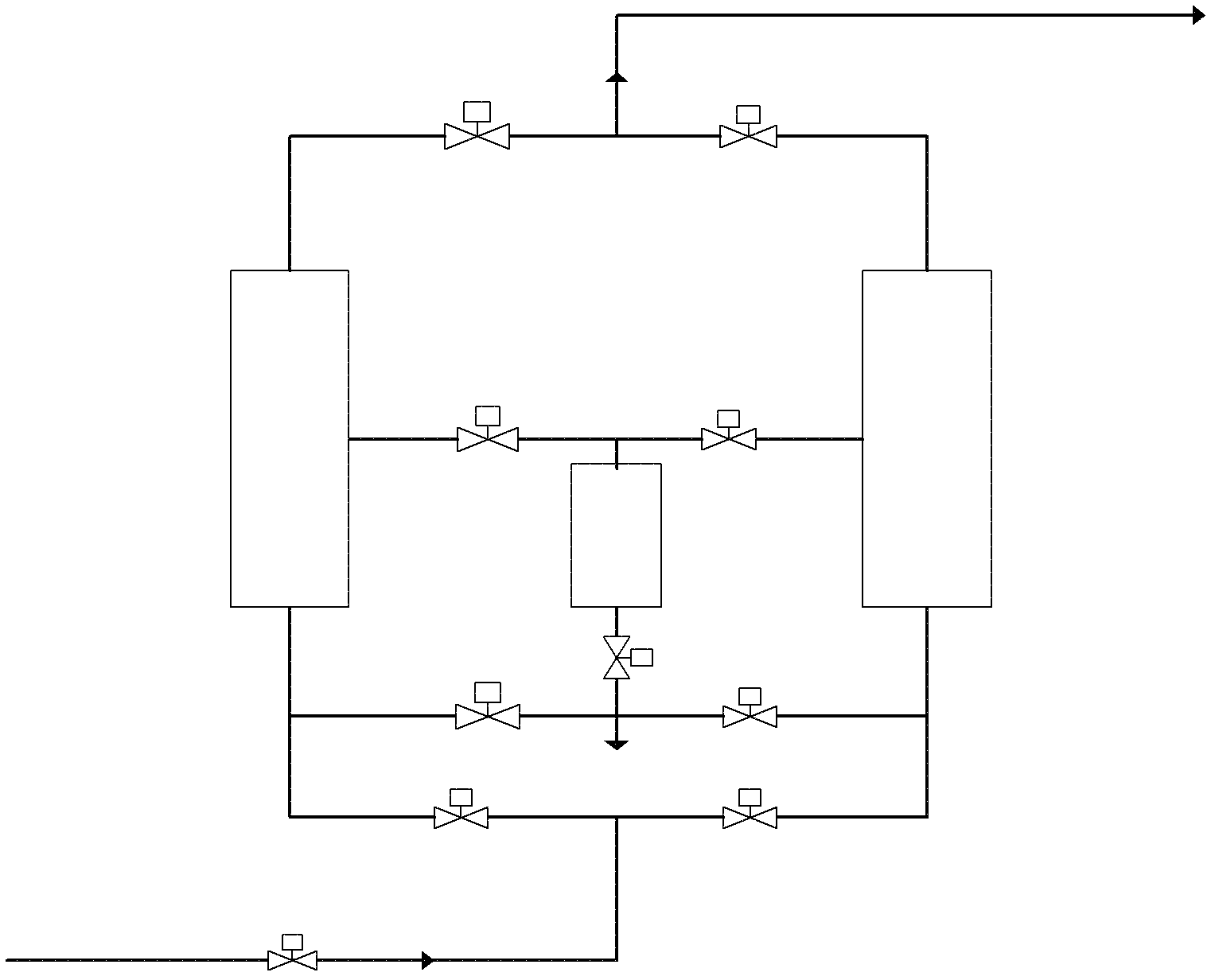
[0045] see Figure 4 , a pressure swing adsorption gas separation device, comprising two adsorption towers 10A and 10B, and a compressed air storage tank 10D and a nitrogen product gas storage tank 10E, an adsorption sub-tower 10C (adsorption sub-tower 10C) is arranged between the two adsorption towers Volume is 20% of adsorption tower volume), described adsorption sub-tower 10C is connected with adsorption tower 10A and 10B by pipeline and valve 203,204,205,206, is filled with molecular sieve adsorbent in adsorption sub-tower 10C, two adsorption towers The tower top and the bottom of the tower are respectively connected by pipeline and valve (that is, the tower top of adsorption tower 10A and 10B is connected by pipeline and valve 201,202, and the tower bottom of adsorption tower 10A and 10B is connected by pipeline and valve 207,208), adsorption The tower top of tower 10A is connected with the tower middle of adsorption tower 10B by pipeline and valve 211, and the tower top ...


PUM


Abstract

The invention discloses a pressure-variable adsorption gas separation device, which comprises two or more adsorption towers, wherein the tops of every two adjacent adsorption towers, and the bottoms of every two adjacent adsorption towers are respectively connected by pipelines and valves, and an auxiliary adsorption tower is arranged between every two adjacent adsorption towers, and is connected with the two adjacent adsorption towers through pipelines and valves; and an adsorbent is filled in each auxiliary adsorption tower, and the top of each adsorption tower is connected with the middles of the adjacent adsorption towers through pipelines and valves. By changing a pressure equalizing component and additionally arranging the auxiliary adsorption towers, a pressure equalizing method in the prior process is improved, so that the adsorption of gas to be purified in an adsorbent bed layer is reasonable to great extent, the utilization efficiency of the adsorbent is greatly improved, the breakthrough time of the adsorption tower is prolonged, and the gas production rate of the adsorbent in the towers is improved. As validated by implementation, the device is very suitable for preparing high-purity gases.

Description


Claims


Application Information

Patent Timeline
Owner 长兴山立化工材料科技有限公司
Why Eureka
Try Eureka