
Processing device used for inner wall of barrel body

A processing device and barrel body technology, applied in the field of mechanical processing, can solve the problems of reduced processing accuracy, inability to apply curved surface processing, inability to meet use requirements, etc., and achieve the effects of reducing processing difficulty and improving production efficiency.

Active Publication Date: 2012-07-25
NINGBO JIANGDONG KEREN MACHINERY
View PDF8 Cites 3 Cited by
  • Summary
  • Abstract
  • Description
  • Claims
  • Application Information

AI Technical Summary

Problems solved by technology

However, the above-mentioned processing device and method cannot be used for the processing of curved surfaces. Due to the variation of the height and angle of the curved surface to be processed, it is impossible to use a processing device and a tool with a fixed angle to realize processing, and the processing device of the prior art cannot adjust the processing Height and angle, not suitable for surface processing
Due to the processing of the inner wall of the barrel, the tool on the processing device needs to go deep into the barrel, and the drive of the tool needs to be completed by a power motor, and the angle of the tool needs to be adjusted according to the height and angle of the curved surface. The power motor and tool in the prior art The linear and rigid connection of the rotating shaft can no longer meet the requirements of this occasion
In addition, during the processing of the processing device on the inner wall of the barrel, the processing device moves on the linear guide rail. At this time, the linear guide rail is supported by the single-point roller on the base to solve the cantilever problem of the linear guide rail. However, as the linear guide rail drives the processing If the device continues to move forward, the cantilever will still sag due to its own gravity, which will affect the straightness of the linear guide and reduce the machining accuracy

Method used


Image

  • Processing device used for inner wall of barrel body
  • Processing device used for inner wall of barrel body
  • Processing device used for inner wall of barrel body

Examples


Embodiment Construction

[0014] The present invention will be further described below in conjunction with the accompanying drawings and specific embodiments.

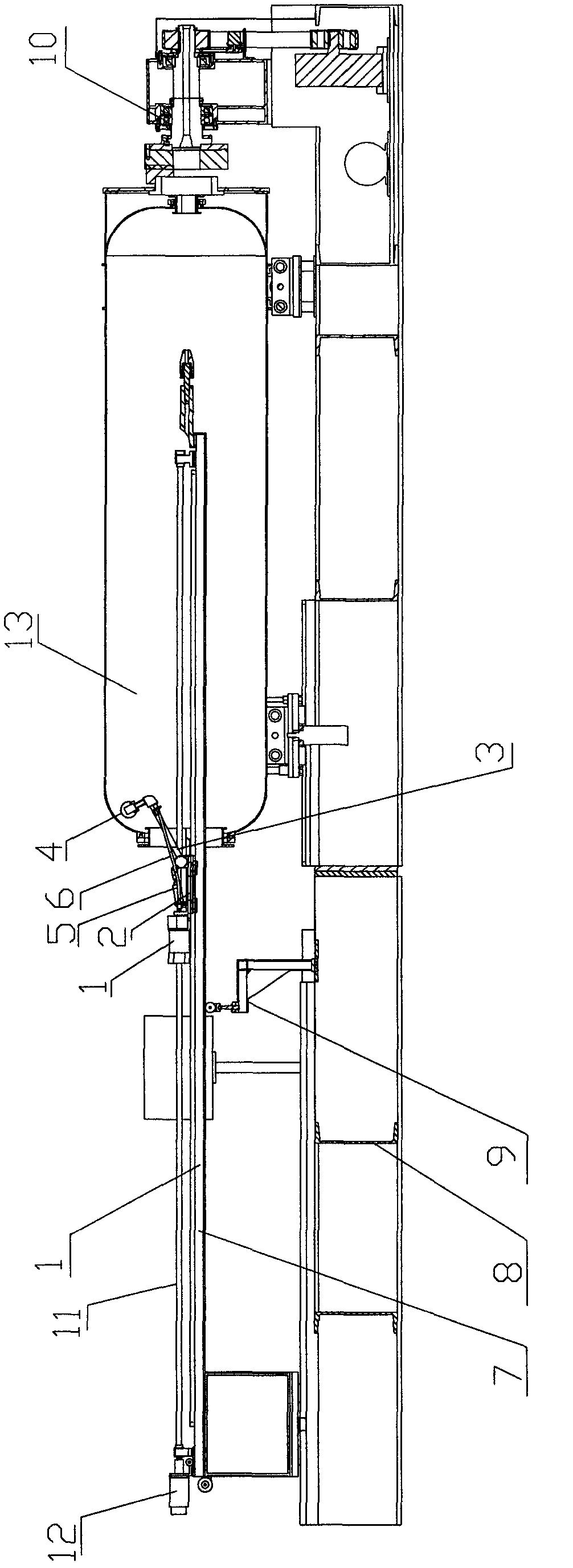
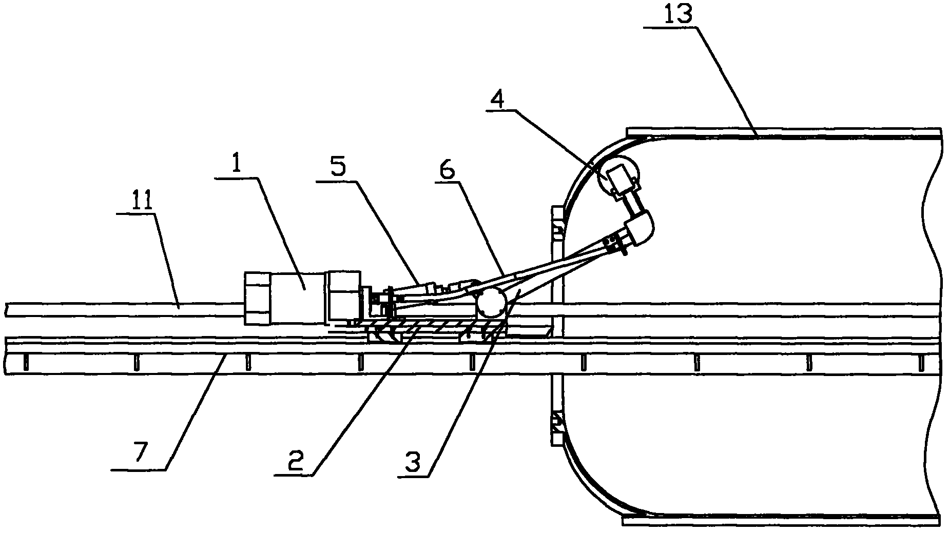
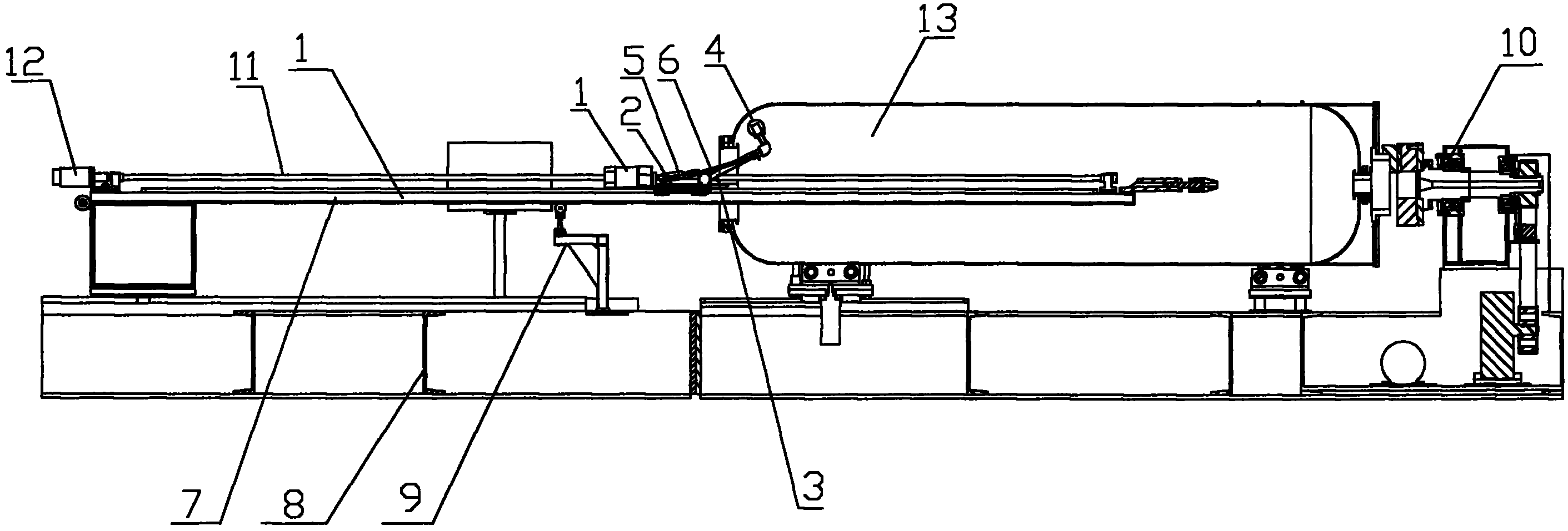
[0015] Such as figure 1 As shown, the processing device for the barrel inner wall of the present invention includes a power motor 1, a base plate 2, a connecting rod 3, a blade 4 and a cylinder 5 driving the connecting rod 3, one end of the connecting rod 3 is connected with the cylinder piston, A blade 4 is installed on the other end, and the position near one end of the cylinder on the connecting rod 3 is hinged with the base plate 2 , and the output shaft of the power motor 1 is connected with the blade 4 .

[0016] The processing device also includes a flexible shaft 6, one end of the flexible shaft 6 is connected to the output shaft of the power motor 1, and the other end of the flexible shaft 6 is connected to the blade 4; the flexible shaft 6 includes a flexible metal shaft and a plastic sleeve , the plastic sleeve is wrapped outside th...


PUM


Abstract

The invention discloses a processing device used for an inner wall of a barrel body. The processing device comprises a power motor (1), a base plate (2), a connecting rod (3), a blade (4) and a driving mechanism that is used for driving the connecting rod (3), wherein one end of the connecting rod (3) is connected with a piston of an air cylinder, the blade (4) is arranged on the other end of the connecting rod (3), one end of the connecting rod (3), which is arranged near the driving mechanism, is articulated with the base plate (2), and an output shaft of the power motor (1) is connected with the blade (4). The processing device also comprises a flexible shaft (6), wherein one end of the flexible shaft (6) is connected with the output shaft of the power motor (1), and the other end of the flexible shaft (6) is connected with the blade (4). The processing device can be used for processing the inner wall of the barrel body through the regulation for the processing height and the processing angle, thereby not only improving the production efficiency but also reducing the processing difficulty; moreover, the processing device can effectively process the curved surface of the inner wall of the barrel body and can transmit torque of the motor from a great distance without the affection of curvature.

Description

technical field [0001] The invention relates to the field of mechanical processing, in particular to a processing device for the inner wall of a barrel. Background technique [0002] In the field of mechanical processing, especially the processing of the barrel body, when the diameter of the barrel body is smaller than the diameter of the barrel body, the mouth of the barrel body will form a curved surface with the inside of the barrel. Therefore, in addition to the processing of the inner wall of the barrel body, it is also necessary to Process the curved surface formed between the mouth of the barrel body and the inside of the barrel. If only the cylindrical inner wall of the barrel is processed, the position and angle of the blade only need to be adjusted so that the entire processing device can process the inner wall on the straight guide rail. However, the above-mentioned processing device and method cannot be used for the processing of curved surfaces. Due to the vari...

Claims


Application Information

Patent Timeline
IPC IPC(8): B23D79/00B23Q5/10B23Q5/40B23Q15/22
Inventor 柯明
Owner NINGBO JIANGDONG KEREN MACHINERY
Learn More