Transfer making machine

A technology of fonts and bottom plates, applied in decorative art, engraving, etc., can solve the problems of impossible engraving, labor and time-consuming, and difficult to guarantee positioning accuracy, etc., and achieve the effect of high engraving efficiency, wide practical range, and convenient operation

Inactive Publication Date: 2012-07-25
SHIHLIN ELECTRIC CHANGZHOU
View PDF6 Cites 5 Cited by
  • Summary
  • Abstract
  • Description
  • Claims
  • Application Information

AI Technical Summary

Problems solved by technology

This method of engraving has certain limitations. When the engraving line to be engraved or the angle between the starting point and the end point of the word is too large, it is impossib

Method used


Image

  • Transfer making machine
  • Transfer making machine
  • Transfer making machine

Examples


Embodiment Construction

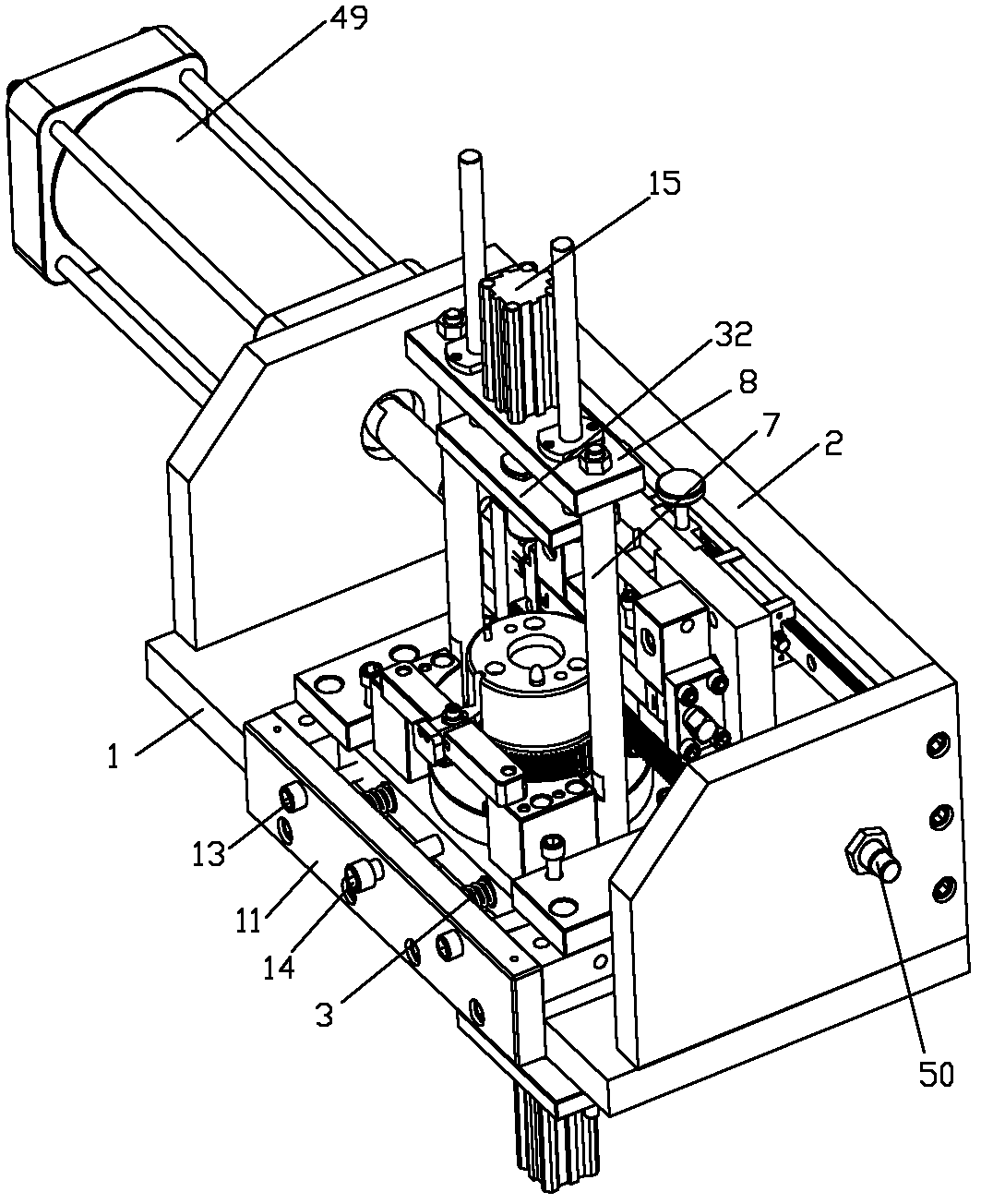
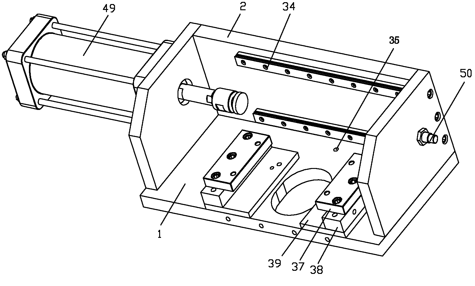
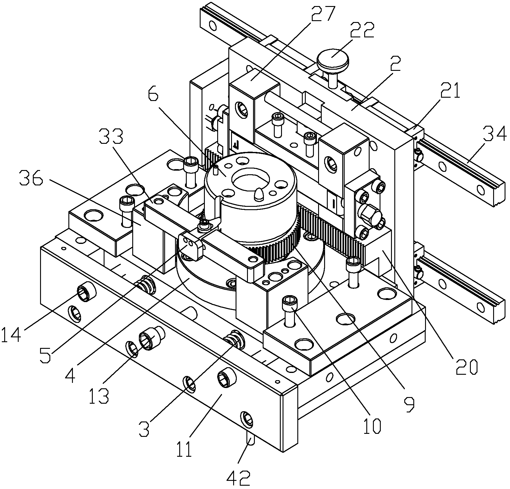
[0025] refer to Figure 1 to Figure 3 , the transformation machine of the present invention uses compressed air as the power to rotate the cylindrical workpiece, and while the cylindrical workpiece is rotating, the pre-made characters are distributed along the circumference of the workpiece and engraved on the outer surface of the cylindrical workpiece, so it is called "Zhuan". machine. The specific structure of the transformation machine of the present invention is as follows:

[0026] The bottom plate 1 is provided with a support plate 2, and the side wall of the support plate is slidably fitted with a skateboard assembly that can move along the left and right directions of the bottom plate. The transmission rack 20 is located below the type support device. The base plate is provided with a bearing seat 4, and the base plate 1 is provided with a through hole for the bearing seat 4 to pass through. The mandrel 40 is arranged in the bearing housing 4 , a transmission gear 9...


PUM


Abstract

The invention discloses a transfer making machine. A supporting plate is arranged on a bottom plate. A sliding plate assembly capable of moving along the left-and-right direction of the bottom plate is in slide fit with the side wall surface of the supporting plate. A transmission rack and a matrix supporting device are arranged on the lateral surface of the sliding plate assembly, which is deviated from the supporting plate. The transmission rack is positioned below the matrix supporting device. A matrix is arranged in the matrix supporting device. A bearing seat is arranged on the bottom plate. A spindle is arranged in the bearing seat. A transmission gear and a flywheel positioning seat are respectively and circumferentially fixed together with the spindle. The flywheel positioning seat is positioned above the transmission gear. The transmission gear is meshed with the transmission rack. The transfer making machine replaces conventional stamping equipment to process clear characters on a cylindrical part. The characters have consistent depths. The accuracy of engraved lines and engraved characters, which are distributed along the circumference at a regulated angle can reach the range of less than plus and minus 0.5 degree.

Description

technical field [0001] The invention relates to a device for engraving or lettering on the outer peripheral surface of a workpiece, in particular to a turning machine. Background technique [0002] At present, the engraving of lines and lettering with a depth of more than 0.2mm on the surface of a cylindrical workpiece is mainly done by using a punch through a mold. Generally, the lower mold is used to position the workpiece, and the upper mold is used to position the font. The shape of the font needs to be made to match the workpiece. Fitted arc shape. This method of engraving has certain limitations. When the engraved line to be engraved or the angle between the starting point and the end point of the word is too large, it is impossible to engrave clearly. It often needs to be divided into multiple engravings, which is not only difficult to guarantee the positioning accuracy, but also labor-intensive and time-consuming. Contents of the invention [0003] In view of the...

Claims


Application Information

Patent Timeline
IPC IPC(8): B44B3/04
Inventor 谢磊丛爱平恽贤伟
Owner SHIHLIN ELECTRIC CHANGZHOU
Why Eureka
Try Eureka