Steel self-stacking tray

A pallet and stacking technology, which is applied in the field of steel self-stacking pallets, can solve problems such as high cost, inconvenient adjustment of cargo location, and difficulty in overall relocation, and achieve the advantages of convenient use of the plane, simple and easy technical support, and investment saving Effect

Inactive Publication Date: 2012-07-25
李育霖
View PDF1 Cites 8 Cited by
  • Summary
  • Abstract
  • Description
  • Claims
  • Application Information

AI Technical Summary

Problems solved by technology

Fixed multi-layer special shelves have large initial investment and high cost and become permanent equipment once installed. It is inconvenient to adjust the storage position or the overall relocation is difficult or even scrapped.

Method used


Image

  • Steel self-stacking tray
  • Steel self-stacking tray
  • Steel self-stacking tray

Examples


Embodiment 1

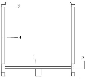
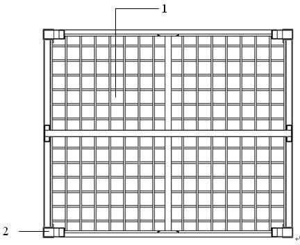
[0038] refer to Figure 1 to Figure 9 , The steel built-in pole self-stacking pallet is composed of a steel pallet, a pole socket, a tray deck, a stacking pole, and a pole deck. [Among them, the steel tray is integrated with the pole socket and the tray holder (referred to as the tray); the stacking pole and the pole holder are integrated (referred to as the pole). ]

[0039] The stacking pole can be freely inserted and pulled out in the pole socket.

[0040] When the tray is used alone, there is no need to insert the pole. When the pallet needs to be self-stacked, insert the 4 poles into the pole socket to form a pallet rack. The forklift drops the second pallet into the pole holder to complete the second-layer stacking of pallets. According to the needs of the pallet stacking height and the lifting height of the forklift, the multi-layer stacking is completed in sequence.

[0041] The tray holder and pole holder are bidirectionally self-locking in the same plane to ensu...

Embodiment 2

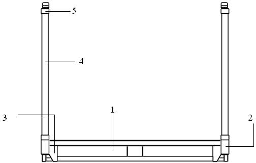
[0043] refer to Figure 10 to Figure 18 , The external pole self-stacking pallet is composed of a steel pallet, a pallet deck, a stacking pole, and a pole deck. [In which the steel pallet is integrated with the pallet holder (referred to as the pallet); the stacking pole and the pole holder are integrated (referred to as the pole)].

[0044] The stacking poles can be freely inserted and pulled out from the tray holder.

[0045] The tray holder and pole holder are bidirectionally self-locking in the same plane to ensure reliable connection and fixation between the tray and the pole.

[0046] When the tray is used alone, there is no need to insert the pole. When pallets need to be self-stacked, insert 4 poles into the pallet holder to form a pallet shelf, and the forklift will drop the second pallet into the pole holder to complete the second-layer stacking of the pallet. According to the needs of the pallet stacking height and the lifting height of the forklift, the multi-la...


PUM


Abstract

The invention discloses a steel self-stacking tray, which comprises steel trays (1), a plurality of supporting rod sockets (2), tray fastening seats (3), stacking supporting rods (4) and supporting rod fastening seats (5). The supporting rod sockets (2) are arranged at the outer edges of the steel-made trays (1), the tray fastening seats (3) are arranged at the bottoms of the steel-made trays (1), one ends of the stacking supporting rods (4) are matched with the supporting rod inserting seats (2) and inserted into or pulled out from the supporting rod sockets (2), the other ends of the stacking supporting rods (4) are provided with the supporting rod fastening seats (5). According to the conditions of warehouses and forklifts, at least two layers of stacking can be realized without purchasing and mounting special multi-layer goods shelves by the aid of the steel self-stacking tray, planes can be used more conveniently and flexibly. Besides, the steel self-stacking tray is widely applicable to tray storage and transport of factories, warehouses and transport tools, and provides a simple and easy product and technical support for conventional (newly built) logistics facility modification (construction) and technology upgrading, and investment on special multi-layer goods shelves can be greatly saved.

Description

technical field [0001] The invention relates to the field of logistics, in particular to a steel self-stacking pallet. Background technique [0002] At present, most of the traditional pallet operations (except for automated three-dimensional warehouses) use forklifts to move horizontally and stack them on special fixed multi-layer shelves. The fixed multi-layer special shelf has a large initial investment and high cost and becomes a permanent equipment once installed. It is inconvenient to adjust the storage position or the overall relocation is difficult or even scrapped. [0003] At present, logistics palletization has become the only way for the transformation and upgrading of the logistics industry. There is an urgent need to reform and innovate traditional pallet products and operating technologies, and provide low investment, quick results, improve efficiency, and reduce costs for traditional, old factories, warehouses (including new) logistics facility renovation (...

Claims


Application Information

Patent Timeline
IPC IPC(8): B65D21/032B65D19/26B65D19/38
Inventor 李育霖
Owner 李育霖
Why Eureka
Try Eureka