Public exhaust passage

A technology for exhaust ducts and air intakes, applied in vertical pipes, building components, buildings, etc., can solve the problems of expensive freight, heavy weight, difficult waterproofing, etc., to ensure permanent use, ensure exhaust efficiency, The effect of easy waterproof treatment

Inactive Publication Date: 2012-07-25
张琦
View PDF6 Cites 8 Cited by
  • Summary
  • Abstract
  • Description
  • Claims
  • Application Information

AI Technical Summary

Problems solved by technology

[0003] (1) The gap between the outer wall of the pipe and the wall is generally between 1 and 2.5 cm, so it is difficult to seal it with grouting and difficult to deal with waterproofing
[0004] (2) The wall thickness of the pipe is generally 1-1.5cm. Since the gap between the pipe and the wall is difficult to seal, especially at the inner corner, the pipe cannot be well combined with the wall, and the durability of the thin-walled pipe cannot be Guarantee the same service life as the building
[0005] (3) The pipeline is large, heavy, expensive in freight, difficult in installation and high in cost

Method used


Image

  • Public exhaust passage
  • Public exhaust passage
  • Public exhaust passage

Examples


Embodiment 1

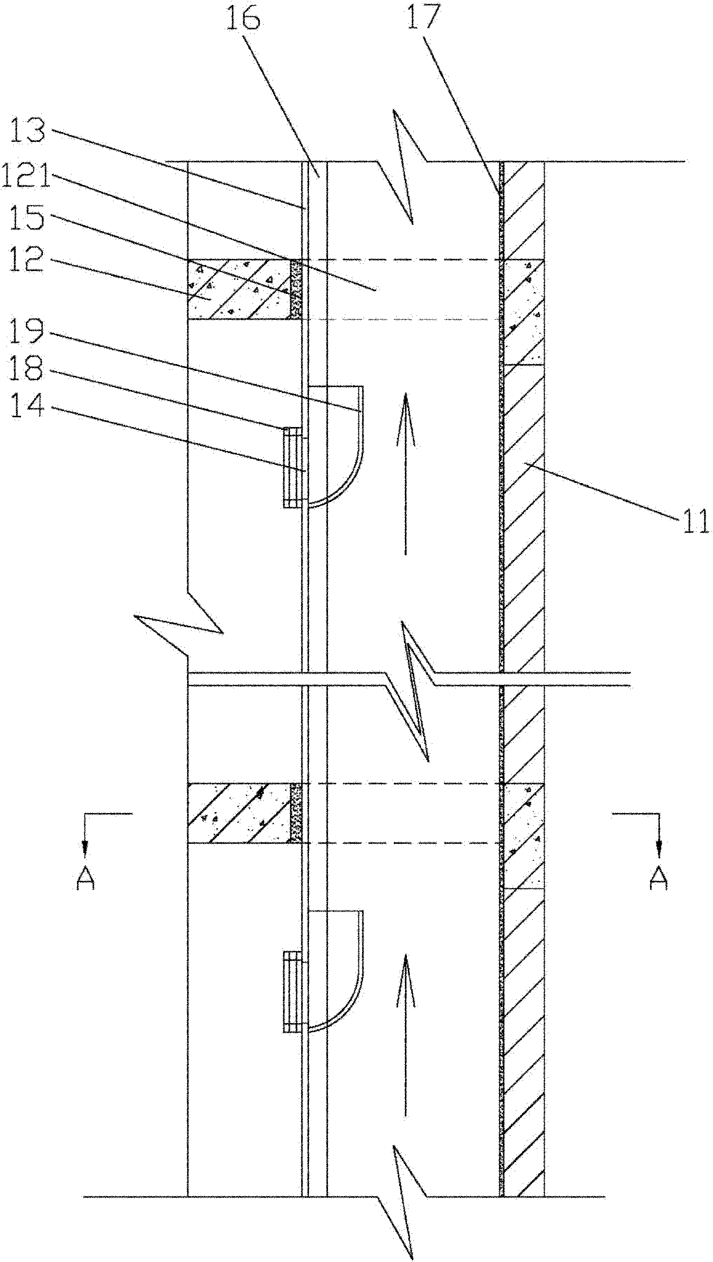
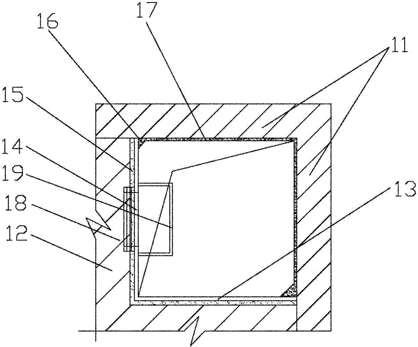
[0033] Such as figure 1 and figure 2 As shown, the common exhaust duct provided by the first embodiment is installed at the inner corner 11 of the room, and an opening 121 is opened at the inner corner 11 of each floor 12, and the L-shaped thin-walled structure 13 encloses the opening 121 and the inner corner 11 walls form a common exhaust duct, and several air inlets 14 are provided on the common exhaust duct. Check valves 18 are installed at 14 places of the air inlet, and an upward guiding pipe 19 with an opening is arranged on the inner side of the air inlet 14.

[0034] In this embodiment, the L-shaped thin-walled structure 13 passes through the hole 121, and the gap between the L-shaped thin-walled structure 13 and the floor 12 is filled with cement mortar 15, which ensures effective sealing between the upper and lower floors and the firm and reliable installation of the L-shaped thin-walled structure .

[0035] In this embodiment, a check valve 18 is installed at the...

Embodiment 2

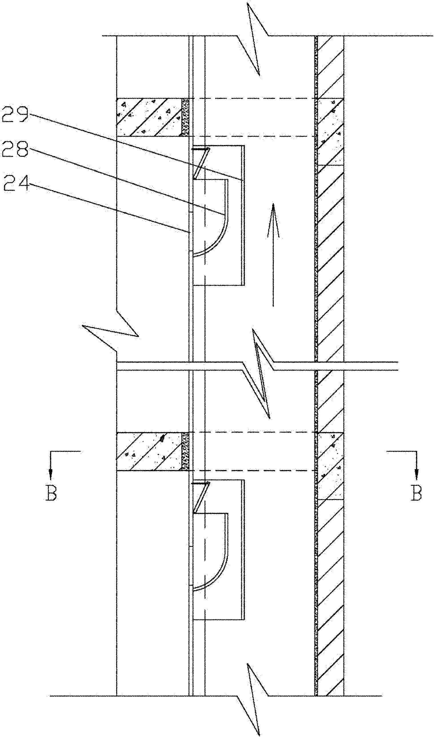
[0044] Such as image 3 and Figure 4 As shown, compared with Embodiment 1, the difference of Embodiment 2 is that a fire damper 28 and a Venturi plate 29 are installed inside the air inlet 24, thereby ensuring that when a fire occurs, the fire damper 28 operates and the passage is cut off. Prevent fire from spreading. The Venturi plate 29 improves the pressure-changing air extraction function of the common exhaust duct system, so that the exhaust gas can be discharged more smoothly. The similarities will not be repeated here.

Embodiment 3

[0046] Such as Figure 5 and Figure 6 As shown, the common exhaust duct provided by the third embodiment is installed at the inner corner 31 of the room, and an opening 321 is opened at the inner corner 31 of each floor 32, and an L-shaped thin-walled structure 33 is installed between each floor 32 , the L-shaped thin-walled structure 33 encloses the wall of the hole 321 and the inner corner 31 to form a common exhaust duct, and the common exhaust duct is provided with a number of air inlets 34, and a fire damper 36 is installed at the air inlet 34.

[0047] In this embodiment, the L-shaped thin-walled structure 33 is installed on the floor 32, that is, the L-shaped thin-walled structure 33 does not need to pass through the opening 321. This installation method solves the self-supporting problem of the L-shaped thin-walled structure 33, that is, the floor 32 The self-weight of the L-shaped thin-walled structure 33 can be supported.

[0048] In this embodiment, the L-shaped ...


PUM


Abstract

The invention provides a public exhaust passage which is arranged at the internal corner of a room. A tunnel opening is arranged in a floor slab at the internal corner, the public exhaust passage is formed as follows: a thin wall structure passes through the tunnel opening or is arranged on the floor slab to enclose the tunnel opening and part of the wall surface. A plurality of air inlets are arranged on the public exhaust passage, and function valves are arranged at the air inlets. Waste gas passes through an exhaust device and is discharged into the public exhaust passage through the function valves and is discharge out from an outlet at the top of the public exhaust passage. The public exhaust passage ensures the effect of an exhaust system of a cement mortar thin wall tube in the prior art, avoids the problem of a gap between the existing pipeline wall and the wall surface, ensures the use permanency of the exhaust system, facilitates the waterproof management, and is simple and reliable in structure, convenient to construct and low in cost.

Description

technical field [0001] The invention relates to a shared exhaust system, in particular to a shared exhaust duct suitable for high-rise and super high-rise buildings. Background technique [0002] At present, the manufacturing method of the shared exhaust ducts of kitchens and bathrooms in buildings is as follows: according to national standards and industry standards, this field is to first manufacture thin-walled (1.0-1.5cm) pipes with a rectangular cross section of cement mortar, and then use the Cement mortar prefabricated thin-walled pipes are vertically assembled from the reserved openings in the floor through the openings from bottom to top to form a common exhaust duct. Although this method of manufacturing and installing the shared exhaust duct belongs to the general standard operation in this field, the following problems still exist: [0003] (1) The gap between the outer wall of the pipe and the wall is generally between 1 and 2.5 cm, so it is difficult to seal i...

Claims


Application Information

Patent Timeline
Patent Type & Authority Applications(China)
IPC IPC(8): E04F17/02
Inventor 张琦
Owner 张琦
Why Eureka
Try Eureka