Non-planar network fracturing control method for fractured reservoir

A control method, non-planar technology, applied in the direction of earth-moving drilling, production of fluids, wellbore/well components, etc., can solve problems such as difficulty in forming main fractures

Inactive Publication Date: 2012-07-25
ORIENT BAOLIN TECH DEV BEIJING
View PDF1 Cites 92 Cited by
  • Summary
  • Abstract
  • Description
  • Claims
  • Application Information

AI Technical Summary

Problems solved by technology

[0002] For fractured reservoirs with well-developed natural fractures, during hydraulic fracturing, since the tensile strength of natural fractures is lower than that of rock, under a certain net press

Method used


Image

  • Non-planar network fracturing control method for fractured reservoir
  • Non-planar network fracturing control method for fractured reservoir
  • Non-planar network fracturing control method for fractured reservoir

Examples


Embodiment 1

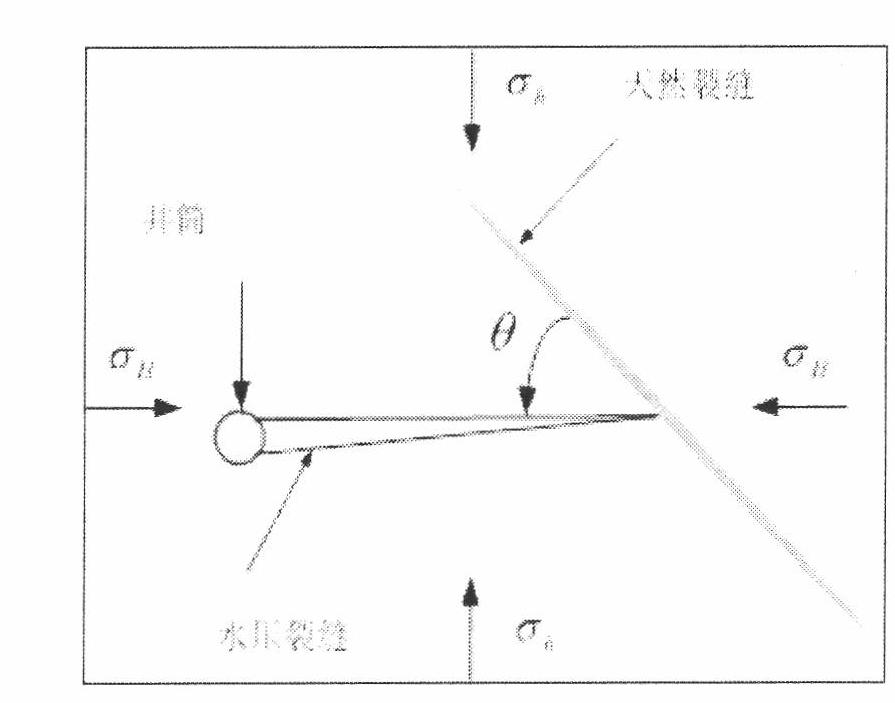
[0170] The fracturing interval of Well PuG101 is siltstone and fine sandstone in lithology, the reservoir space is mainly pore type, intergranular pores and dissolution pores are developed, natural fractures are developed in the core, the maximum principal stress orientation is NE45°, FMI imaging logging shows that nearly The angle between the azimuth of the wellbore natural fracture and the azimuth of the maximum principal stress is 40°. The fractured well section is 3700.9-3737.2m, the thickness is 25.2m / 3 layers, the logging interpretation porosity is 2-3%, the acoustic time difference is less than 60us / ft, and the permeability is less than 0.1×10⁻³μm2, interpreted as gas-bearing layers and Poor atmosphere. The perforated sections are 3700.9-3707.0m, 3711.1-3717.0m, 3724.0-3737.2m respectively. The perforation density is 8 holes / m, the phase angle is 60°, and the holes are helically arranged.

[0171] The core test shows that the maximum horizontal principal stress value ...

Embodiment 2

[0177] Shallow 001-6-X4 well fractured interval 1803.8-1819.4m, fine sandstone lithology. All the other steps are the same as in Example 1.

[0178] Log comprehensive interpretation result table

[0179]

[0180] Figure 25 It is the integrated well logging curve of the fourth member of Xu (well section 1790-1830m) in Well Danqian 001-6-X4 in Example 2;

[0181] Figure 26 It is the test fracturing construction curve and pressure drop analysis result of embodiment 2;

[0182] Figure 27 It is the construction curve and pressure drop analysis results of the near-wellbore network fracture stage of embodiment 2;

[0183] Figure 28 It is the construction curve and pressure drop analysis result of the main fracturing stage of embodiment 2;

[0184] The crack monitoring results are as follows Figure 29 as shown, Figure 29 Plane display of all event points for three-stage fracturing (test fracturing, fracture network fracturing, main fracturing);

[0185] Figure 30 ...


PUM

PropertyMeasurementUnit
Young's modulusaaaaaaaaaa

Abstract

The invention discloses a non-planar network fracturing construction control method for a fractured reservoir, which includes the step: firstly, performing pre-fracturing evaluation by (1) obtaining the intrinsic fracture development degree and directions according to FMI (formation micro-scanner image) logging and conventional logging data, (2) determining man-made fracture directions, (3) judging the angle relation between man-made fractures and intrinsic fractures, and (4) judging the non-planar network fracturing formation adequacy; secondly, establishing a stress field inversion constrained optimization model by utilizing a numerical value inversion method combining multi-well constrained optimization and finite elements so as to obtain numerical simulation of three-dimensional geostress states and rock mechanical parameters of a fractured reservoir area; thirdly, selecting corresponding construction parameters, and fracturing strata so as to force the intrinsic fractures and holes to open as large as possible; and fourthly, according to the opened equivalent number and openness of the intrinsic fractures explained by test fracturing, selecting grain sizes and use amount of propping agents matched with the intrinsic fractures or the holes, and leading fracturing fluid carrying the propping agents to enter the intrinsic fractures or the holes.

Description

technical field [0001] The invention relates to a non-planar network fracture fracturing construction control method in a fractured reservoir. Background technique [0002] For fractured reservoirs with well-developed natural fractures, during hydraulic fracturing, since the tensile strength of natural fractures is lower than that of rock, under a certain net pressure condition, natural fractures will preferentially open and connect with each other, resulting in a large amount of fracturing fluid. Filtration loss makes it difficult to form main fractures. Most of the natural fracture systems of this kind of reservoirs appear in groups, often multiple groups of fractures exist at the same time, each fracture is surrounded by other fractures, sometimes cut by other groups of fractures, and there may be lower-level fractures near it. Conventional fracturing mostly uses silt / ceramic slugs to inhibit the opening of natural fractures, and resin particles are also used to treat na...

Claims


Application Information

Patent Timeline
IPC IPC(8): E21B43/267E21B47/002
Inventor 杜林麟陈守雨
Owner ORIENT BAOLIN TECH DEV BEIJING
Why Eureka
Try Eureka