Blasting method controlling damage of damage rings of tunnel
A technology for controlling blasting and tunneling, applied in blasting and other directions, can solve problems such as reducing the service life of tunnels
- Summary
- Abstract
- Description
- Claims
- Application Information
AI Technical Summary
Problems solved by technology
Method used
Image
Examples
Embodiment 1
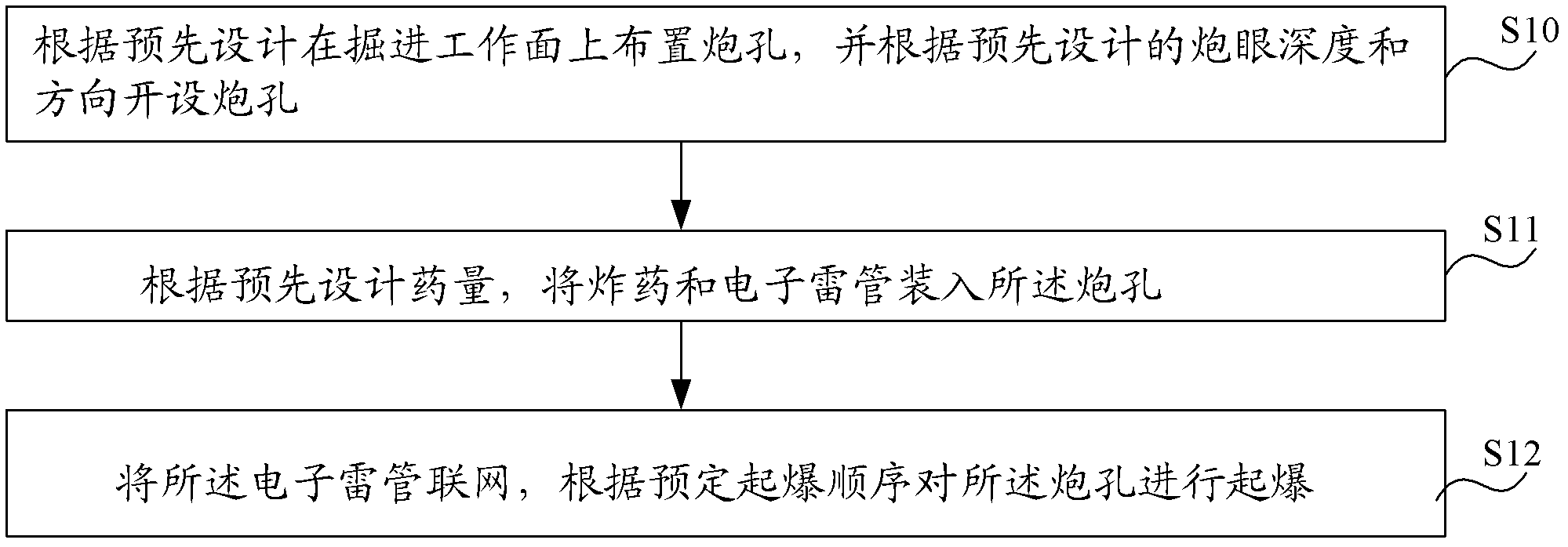
[0021] see figure 1 As shown, the tunnel damage zone damage control blasting method in this embodiment includes steps:
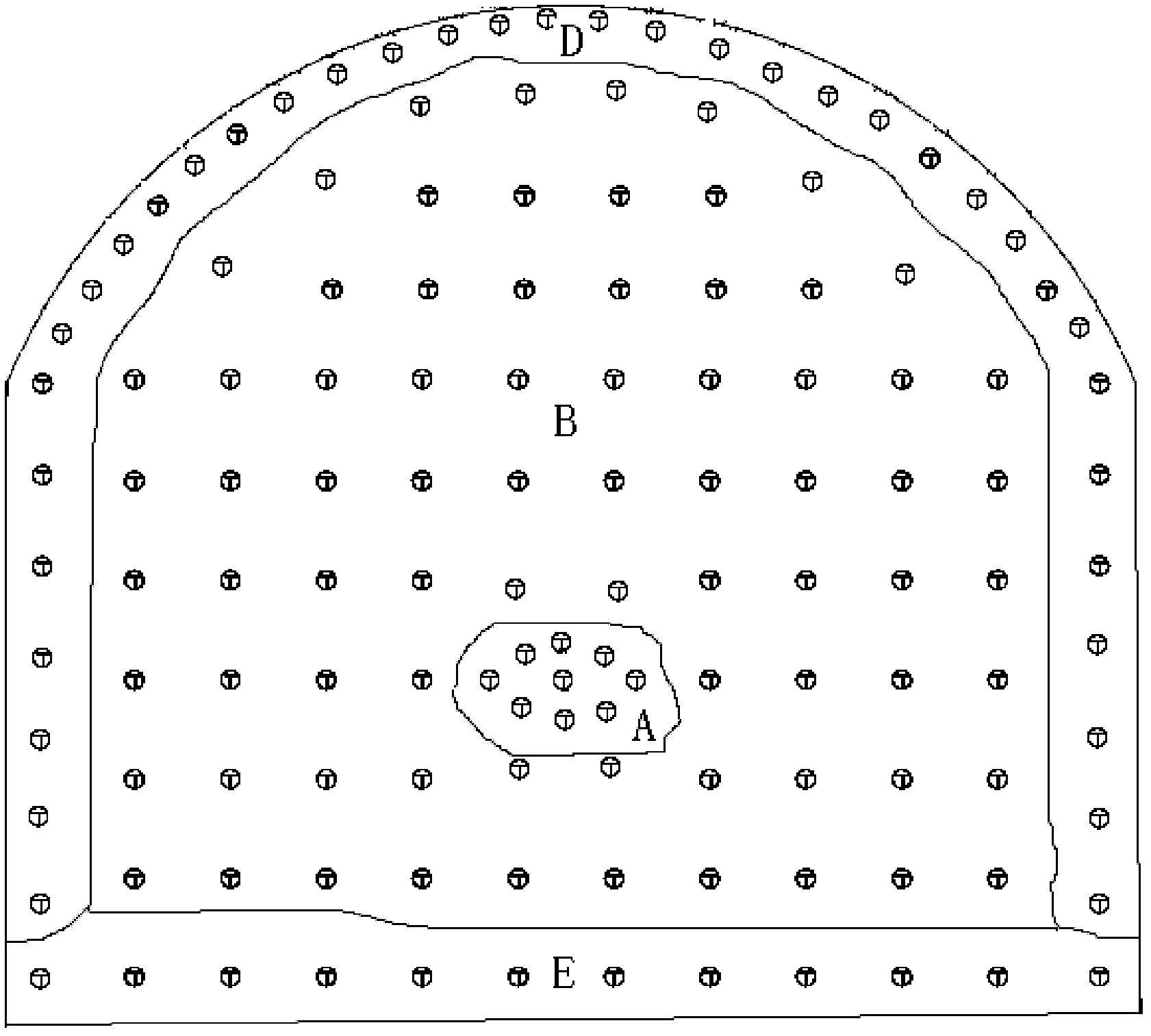
[0022] S10. Arranging blast holes on the excavation face according to the pre-design, and opening blast holes according to the pre-designed blast hole depth and direction, wherein the blast hole types include cut holes, auxiliary holes located on the periphery of the cut holes, Peripheral holes located on the periphery of the auxiliary hole and on the excavation contour line, and bottom holes located on the bottom edge of the tunnel.
[0023] see figure 2 As shown, the area where each cut hole is located forms a cut hole area A, similarly, the area where each auxiliary hole is located forms the auxiliary hole area B, and the area where each peripheral hole is located forms a peripheral hole area D; The area forms the bottom hole area E; the definitions of the cut hole area, the auxiliary hole area, the peripheral hole area and the bottom hole area in the ...
Embodiment 2
[0032] The blasting method for damage control of the tunnel damage circle in this embodiment includes steps:
[0033] S21. Create a blasthole on the excavation face according to the pre-design, wherein the type of blasthole includes a cutout hole, an auxiliary hole located on the periphery of the cutout hole, and an auxiliary hole located on the periphery of the auxiliary hole and on the excavation contour line Perimeter holes, and bottom holes at the bottom edge of the tunnel.
[0034] When opening peripheral holes, peripheral hole angle control technology or rock drills or blasthole angle controllers that can control the blasthole angle of peripheral holes can be used to ensure that there is no overbreak or underbreak.
[0035] S22. Load explosives and electronic detonators into the blast hole according to the pre-designed charge amount.
[0036] S23. Connect the electronic detonators to a network, and detonate the blast holes according to a predetermined detonation sequenc...
Embodiment 3
[0043] The blasting method for damage control of the tunnel damage circle in this embodiment includes steps:
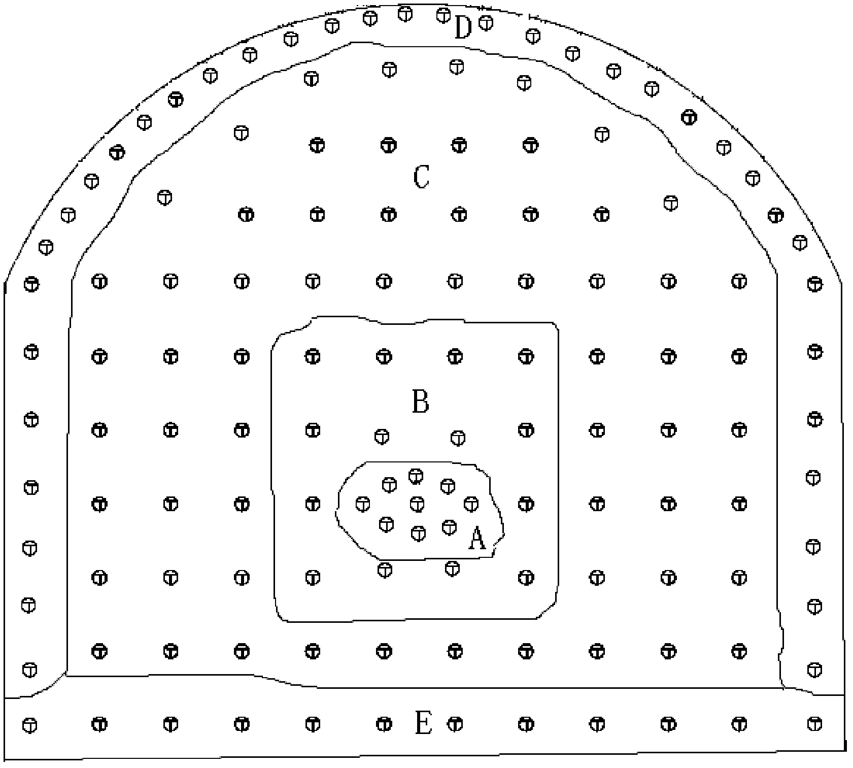
[0044] S30. Arranging blast holes on the excavation face according to the pre-design, and opening blast holes according to the pre-designed blast hole depth and direction, wherein the blast hole types include cut holes, auxiliary holes located on the periphery of the cut holes, The caving hole is located on the periphery of the auxiliary hole, the peripheral hole is located on the periphery of the caving hole and on the excavation contour line, and the bottom hole is located on the bottom edge of the tunnel.
[0045] see image 3 As shown, among them, the region where each of the above-mentioned collapse holes is located forms the region C of the collapse hole.
[0046] S31. Load explosives and an electronic detonator into the blast hole according to the pre-designed charge amount.
[0047] S32. Connect the electronic detonators to a network, and detonate the blast ...
PUM
| Property | Measurement | Unit |
|---|---|---|
| Density | aaaaa | aaaaa |
| Density | aaaaa | aaaaa |
Abstract
Description
Claims
Application Information
 - R&D
- Intellectual Property
- Life Sciences
- Materials
- Tech Scout
- Unparalleled Data Quality
- Higher Quality Content
- 60% Fewer Hallucinations
Browse by: Latest US Patents, China's latest patents, Technical Efficacy Thesaurus, Application Domain, Technology Topic, Popular Technical Reports.
© 2025 PatSnap. All rights reserved.Legal|Privacy policy|Modern Slavery Act Transparency Statement|Sitemap|About US| Contact US: help@patsnap.com


