Wireless infrared electronic fence and working method thereof

An electronic fence and infrared technology, applied to instruments, anti-theft alarms, alarms, etc., can solve problems such as safety needs to be improved, trouble, lack of alarm, disarm, alarm times, alarm date and time, etc., to achieve a perfect protection mechanism , The effect of timely information feedback

Active Publication Date: 2012-07-25
NANJING IOT SENSOR TECH
View PDF5 Cites 8 Cited by
  • Summary
  • Abstract
  • Description
  • Claims
  • Application Information

AI Technical Summary

Problems solved by technology

[0003] Traditional fences generally use infrared detection technology, which uses 220V AC power to convert to DC power to power the infrared transmitter module. This requires laying wires around the fence, which wastes resources and troublesome construction. It only has an alarm function and does not have the ability to record and store abnormal conditions. Real-time status functions such as alarm, disarm, alarm times, alarm date and time, etc., cannot check the dynamic information of the infrared rays emitted by the fence, and cannot find out whether there is an abnormal state in the infrared fence in time, and the safety needs to be improved

Method used


Image

  • Wireless infrared electronic fence and working method thereof
  • Wireless infrared electronic fence and working method thereof
  • Wireless infrared electronic fence and working method thereof

Examples


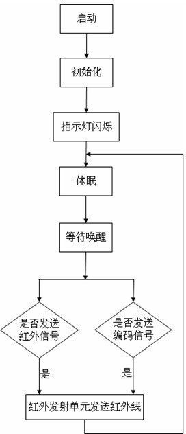
Embodiment Construction

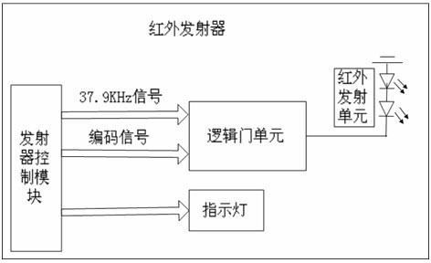
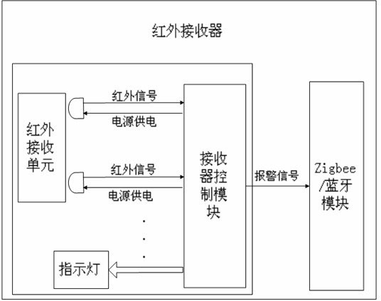
[0024] Such as figure 1 and 2 As shown, the present invention provides a wireless infrared electronic fence, including an infrared transmitter and an infrared receiver, wherein:

[0025] The infrared transmitter includes a transmitter control module, a logic gate unit, an infrared transmitter unit, an indicator light and a transmitter power supply, the logic gate unit and the indicator lamp are respectively connected to the transmitter control module circuit, the logic gate unit is connected to the infrared transmitter unit circuit, and the transmitter The transmitter power supply supplies power to the infrared transmitter.

[0026] The infrared receiver includes an infrared receiving unit, a receiver control module, an indicator light, a Zigbee / Bluetooth module and a receiver power supply. The receiver is powered. Both the main power supply of the transmitter power supply and the receiver power supply come from solar batteries, and a backup battery is connected in parallel...


PUM


Abstract

The invention relates to a wireless infrared electronic fence that is good in safety and capable of realizing remote and wireless real-time monitoring and automatically realizing history recording, and a working method of the wireless infrared electronic fence. The wireless infrared electronic fence comprises an infrared emitter and an infrared receiver which are arranged oppositely. An infrared signal input end and a code signal input end of a logic gate unit in the infrared emitter are connected with corresponding ports of an emitter controller module. An output end of the logic gate unit is connected with a circuit of an infrared emitting unit, and a power supply of the emitter supplies power to connection of the parts. An infrared receiving unit and a Zigbee/Bluetooth module in the infrared receiver are both connected with a control module circuit of a receiver, and the power supply of the receiver supplies power for connection of the parts.

Description

[0001] technical field [0002] The invention relates to an infrared electronic fence, in particular to a wireless infrared electronic fence which can be powered by solar energy and a working method thereof. Background technique [0003] Traditional fences generally use infrared detection technology, which uses 220V AC power to convert to DC power to power the infrared transmitter module. This requires laying wires around the fence, which wastes resources and troublesome construction. It only has an alarm function and does not have the ability to record and store abnormal conditions. Real-time status functions such as alarm, disarm, alarm times, alarm date and time, etc., cannot check the dynamic information of the infrared rays emitted by the fence, and cannot find out whether there is an abnormal state in the infrared fence in time, and the safety needs to be improved. Contents of the invention [0004] The technical problem to be solved by the present invention is to pr...

Claims


Application Information

Patent Timeline
Patent Type & Authority Applications(China)
IPC IPC(8): G08B13/181
Inventor 朱峰朱俊岭朱俊岗余建美
Owner NANJING IOT SENSOR TECH
Why Eureka
Try Eureka