Lead clamping device

A technology of clamping device and wire, which is applied in the direction of cable suspension device, etc., which can solve the problems of easily cracked wire and inconvenient construction

Inactive Publication Date: 2012-07-25
AEROSPACE SCI & IND SHENZHEN GROUP
View PDF4 Cites 16 Cited by
  • Summary
  • Abstract
  • Description
  • Claims
  • Application Information

AI Technical Summary

Problems solved by technology

[0004] The present invention aims to solve the technical problem that the conductor clamping device in the prior art is inconvenient to construct during the process of clamping the conductor and is easy to pinch and crack the conductor, and provides a wire clamping device that is easy to construct and does not easily cause the conductor to be clamped. cracked wire clamp

Method used


Image

  • Lead clamping device
  • Lead clamping device
  • Lead clamping device

Examples


Embodiment Construction

[0021] In order to make the technical problems, technical solutions and beneficial effects solved by the present invention clearer, the present invention will be further described in detail below in conjunction with the accompanying drawings and embodiments. It should be understood that the specific embodiments described here are only used to explain the present invention, not to limit the present invention.

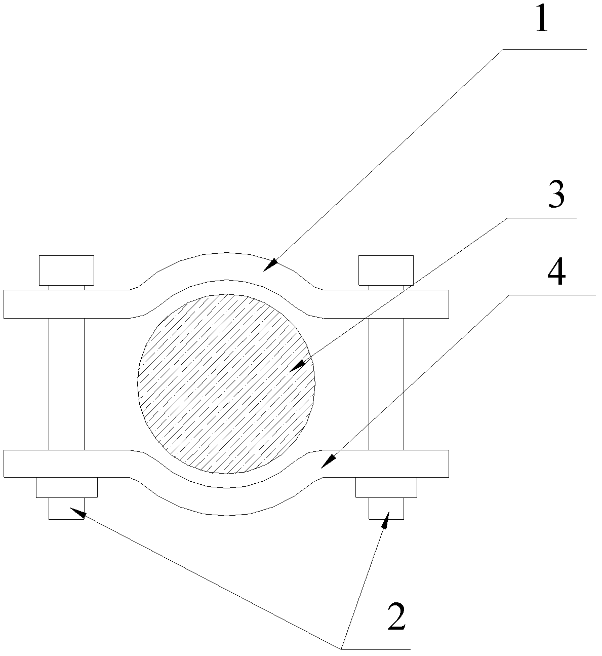
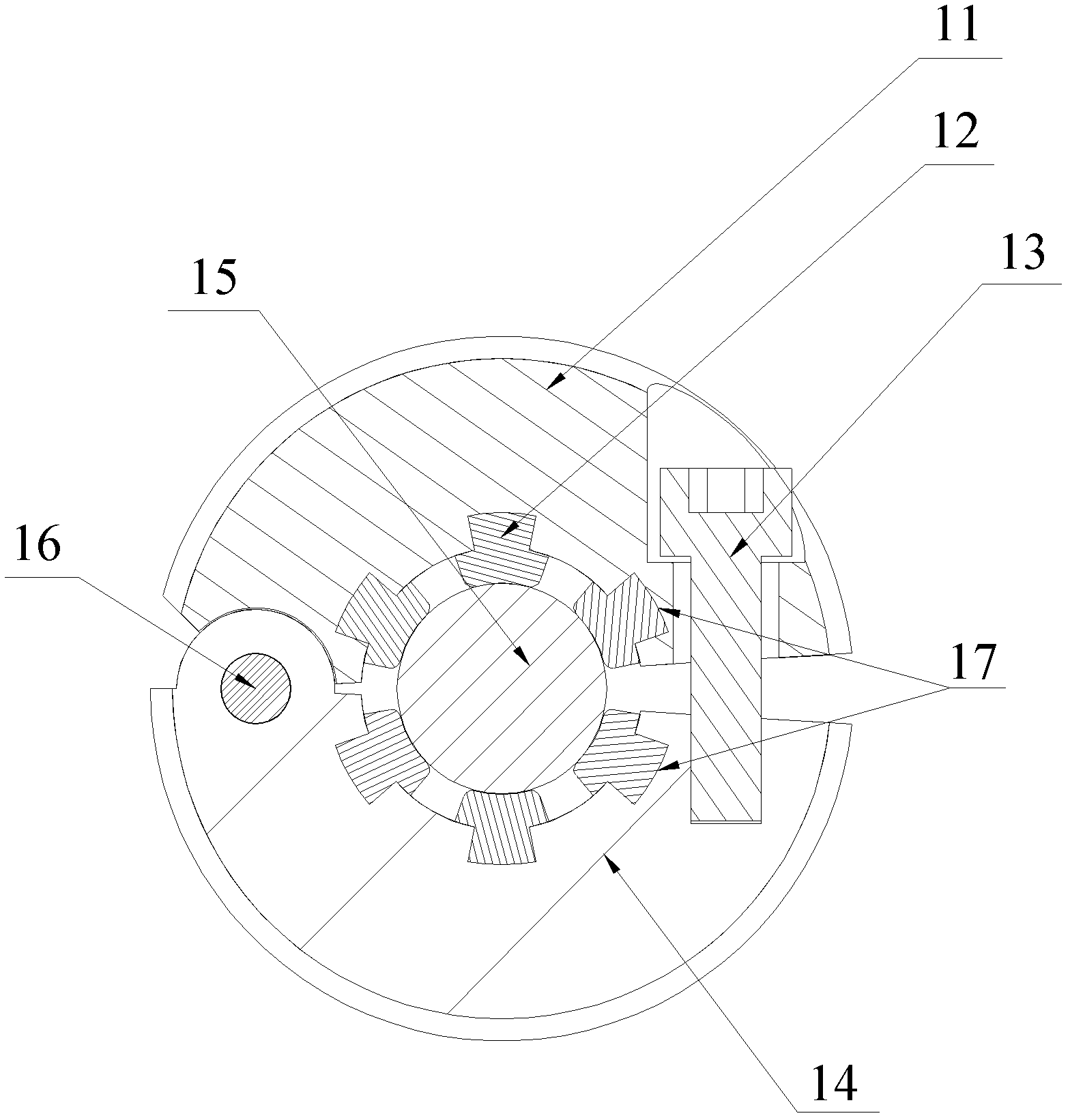
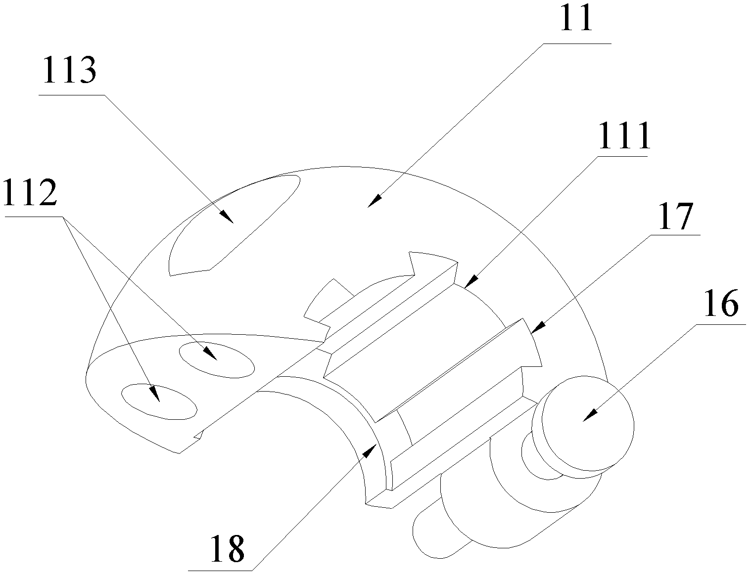
[0022] Such as image 3 As shown, the wire clamping device provided by the present invention includes: a first clamp 11, a second clamp 14 rotatably connected to the first clamp 11, the first clamp 11 and the second clamp 14 can be engaged with each other to form a On the engaging surface, after the first clamp 11 and the second clamp 14 are engaged with each other, a cylindrical space for accommodating the wire 15 is formed inside, and the cylindrical space extends along the axial direction of the cylinder and passes through the wire clamping device. The cylindrical sp...


PUM


Abstract

The invention provides a lead clamping device, which comprises a first fixture and a second fixture. The second fixture is engaged with the first fixture and is rotatably connected with the first fixture, after the first fixture and the second fixture are engaged together, a cylindrical space for holding a lead is formed between the first fixture and the second fixture, extends along axial directions of the first fixture and the second fixture and penetrates through the lead clamping device, and elastic teeth which are peripherally and uniformly distributed are disposed in the cylindrical space, and are used for clamping the lead when the first fixture and the second fixture are engaged together. The lead clamping device in the technical scheme has the advantages that the problem that existing first and second fixtures are easy to fall off due to independent installation of the existing first and second fixtures, installation convenience is improved, the lead is effectively protected, and the problem that a lead cracks due to excessive clamping force of an existing lead clamping device is effectively avoided.

Description

technical field [0001] The invention belongs to a clamping device, in particular to a conductor clamping device of a power transmission line. Background technique [0002] In people's life, electric energy has become an indispensable life energy for people. Electric energy is generated by power stations and delivered to residents in various places through transmission lines. Transmission line conductors, especially high-voltage transmission line conductors, are used to transmit high-voltage power. The stability of their work directly affects the stability of power transmission, which also affects people's daily life. Therefore, the voltage and current of transmission line conductors The monitoring of various power parameters such as electric power has become a crucial task. Therefore, power-related staff will install various monitoring devices on the power conductors as external devices, such as fault indicators, to monitor various power parameters of the conductors in rea...

Claims


Application Information

Patent Timeline
Patent Type & Authority Applications(China)
IPC IPC(8): H02G7/05
Inventor 胡忠伟
Owner AEROSPACE SCI & IND SHENZHEN GROUP
Why Eureka
Try Eureka