

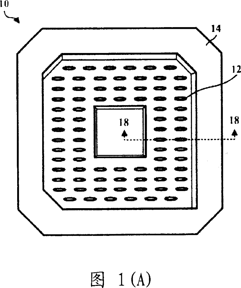
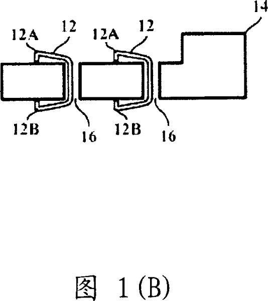
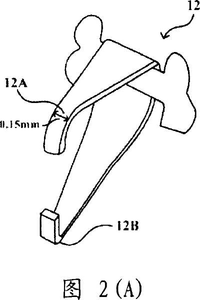
Socket for semiconductor apparatus
A socket and semiconductor technology, applied in the direction of coupling device, connection, fixed connection, etc., can solve the problems of affecting the signal transmission between the chip and the circuit board, the falling off of the C-shaped spring, and the small contact area.
- Summary
- Abstract
- Description
- Claims
- Application Information
AI Technical Summary
Problems solved by technology
Method used
Image

Examples
Embodiment Construction
[0020] One of the main objectives of the present invention is to provide a socket for electrically connecting a chip and a circuit board. The chip includes at least one conductive end, the circuit board includes at least one contact point, and the contact point of the circuit board corresponds to the conductive end of the chip.
[0021] The first preferred embodiment according to the present invention is a socket. Please refer to Figure 3(A). FIG. 3(A) is a schematic diagram of the socket 30 . The socket includes a substrate 34 and at least one conductive post 32 . The substrate 34 further includes at least one hole 36 penetrating through the substrate 34 . Conductive posts 32 are placed through holes 36 . When the socket 30 is placed between the chip and the circuit board, a first end 32A of the conductive post 32 is in contact with the conductive end, and a second end 32B of the conductive post 32 is in contact with the conductive end. The corresponding contact points a...
PUM
 Abstract
Description
Claims
Application Information