Supercharge Your Innovation With Domain-Expert AI Agents!

Magnet aided solenoid for an electrical switch

A solenoid and electric switch technology, which is applied to the parts of the protection switch, the power device inside the switch, the protection switch, etc., can solve the problems of increasing the cost of the solenoid and/or switch, wasting magnetic flux, etc.

Inactive Publication Date: 2012-07-25
TE CONNECTIVITY CORP +1
View PDF6 Cites 0 Cited by
  • Summary
  • Abstract
  • Description
  • Claims
  • Application Information

AI Technical Summary

Problems solved by technology

As the size of the coil, coil housing, and / or other ferromagnetic components increases, the solenoid and / or switch can become unacceptably large and / or heavy
Additionally, an increase in the amount of ferromagnetic material used to manufacture the coil, coil housing, and / or other ferromagnetic components can increase the cost of the solenoid and / or switch
Also, since the physical coupling between the coil and the movable core decreases as the size of the coil increases, at least some of the increased magnetic flux is wasted

Method used


Image

  • Magnet aided solenoid for an electrical switch
  • Magnet aided solenoid for an electrical switch
  • Magnet aided solenoid for an electrical switch

Examples


Embodiment Construction

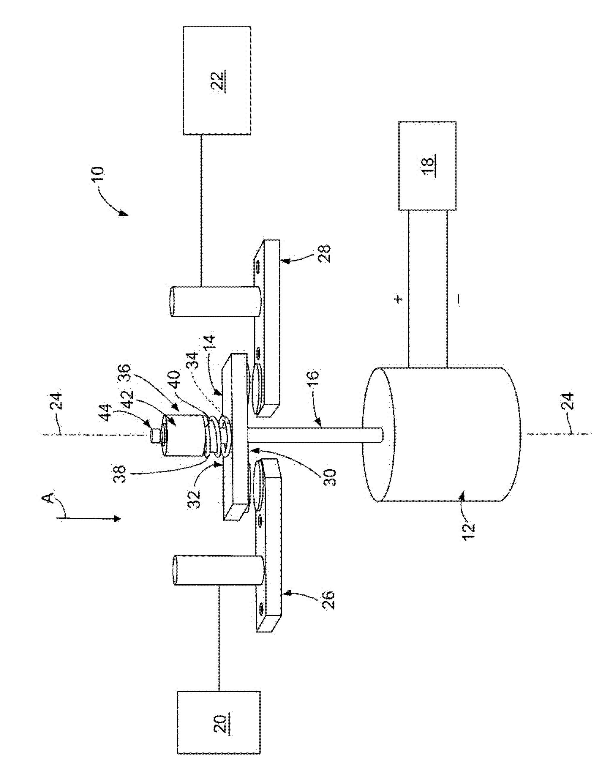
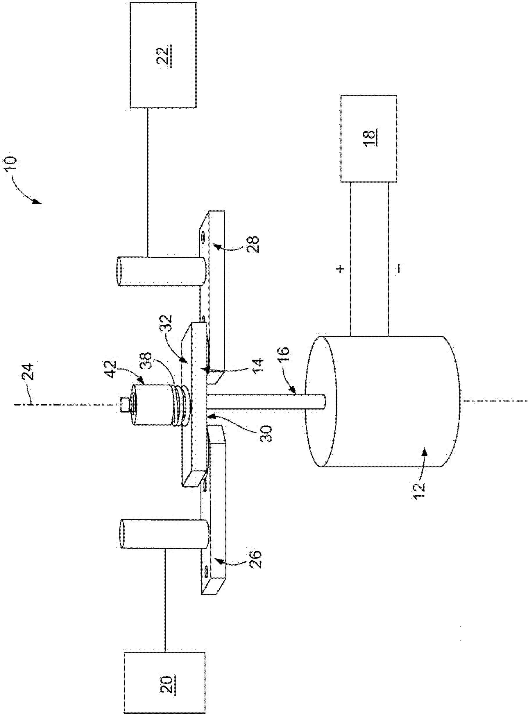
[0012] figure 1 is a schematic diagram of an exemplary embodiment of an electrical switch 10 . The switch 10 includes a solenoid 12 , a movable contact 14 , and an actuation rod 16 connecting the solenoid 12 to the movable contact 14 . The solenoid 12 is electrically connected to a source 18 of electric power for a driving operation of the solenoid 12 . The switch 10 is used to selectively open and close an electrical circuit between two or more electrical devices 20 and 22 . Specifically, as will be described below, the solenoid 12 is configured to move the actuation rod 16 along the central longitudinal axis 24 of the switch 10 . When the actuating rod 16 is moved along the central longitudinal axis 24, the movable contact 14 is figure 1 Open and closed positions shown ( figure 2 ) to move between. In the open position, the movable contact 14 is disengaged from a pair of stationary contacts 26 and 28 electrically connected to a respective one of the electrical devices ...


PUM


Abstract

A solenoid (12) is provided for an electrical switch. The solenoid (12) includes a coil (50) having a passageway extending therethrough along a central longitudinal axis (96). The solenoid (12) also includes a movable core (46) having a coil segment (100) and a magnet segment (102). The coil segment (100) is received within the passageway of the coil (50) such that the coil (50) extends around the coil segment (100). The magnet segment (102) includes a radially outer surface (103) relative to the central longitudinal axis (96) of the passageway of the coil (50). The movable core (46) is movable relative to the coil (50) along the central longitudinal axis (96) such that the coil segment (100) is movable within the passageway of the coil (50) along the central longitudinal axis (96).; A permanent magnet (54) extends around at least a portion of the radially outer surface (103) of the magnet segment (102) of the movable core (46). The movable core (46) is movable along the central longitudinal axis (96) relative to the permanent magnet (54).

Description

technical field [0001] The subject matter described and / or illustrated herein relates generally to electrical switches, and more particularly to solenoids for electrical switches. Background technique [0002] Electrical switches (eg, contactors, relays, etc.) exist today for opening and closing electrical circuits between various electrical devices. For example, electrical switches are sometimes used to electrically connect and disconnect electrical equipment to and from a power source. A typical electrical switch includes an actuator and one or more movable contacts connected to the actuator. Electric current is applied to the actuator to move the movable contact into or out of engagement with a stationary contact that is electrically connected to a corresponding structure in the electrical device. Depending on whether the movable contacts engage or disengage from the stationary contacts, an electrical circuit between electrical devices is thus completed or broken. [0...

Claims


Application Information

Patent Timeline
Patent Type & Authority Applications(China)
IPC IPC(8): H01H71/32H01H1/20H01H3/28
CPCH01H71/322H01H1/20H01H50/546H01H3/28H01H51/2209
Inventor S.帕蒂诺P.维莱亚奈肯N.S.杰苏拉耶R.施万
Owner TE CONNECTIVITY CORP
Features
  • R&D
  • Intellectual Property
  • Life Sciences
  • Materials
  • Tech Scout
  • Unparalleled Data Quality
  • Higher Quality Content
  • 60% Fewer Hallucinations
Learn More