Guidewire

A wire and coil technology applied to wires. Field, can solve problems such as residue, coil falling off, coil spring falling off, etc., to achieve the effect of improving the strength of fixed connection, firmly fixed connection, and not easy to deform

Active Publication Date: 2012-08-01
ASAHI INTECC CO LTD
View PDF9 Cites 8 Cited by
  • Summary
  • Abstract
  • Description
  • Claims
  • Application Information

AI Technical Summary

Problems solved by technology

[0005] However, in the lead wire described in Patent Document 1, since the fixed connection portion on the head side of the head and the coil is formed only on a part of the head, the fixed connection strength is insufficient, and the front end of the coil may fall off from the core wire. And the detached coil will damage the inside of the blood vessel, etc. or remain in the blood vessel
[0006] In addition, the lead wire described in Patent Document 2 uses Au-Sn based solder to fix and connect the core wire and the front end of the coil spring. Although the strength of the fixed connection is slightly increased, since the front end part of the core wire and the coil spring are fixedly connected, the Even if the inside is filled with resin, it cannot be considered that the fixed connection strength is strong enough. Like the lead wire described in Patent Document 1, the tip of the coil spring will fall off from the core wire, and the coil spring will damage the inside of blood vessels such as blood vessels or remaining in the vessel

Method used


Image

  • Guidewire
  • Guidewire
  • Guidewire

Examples


no. 1 approach

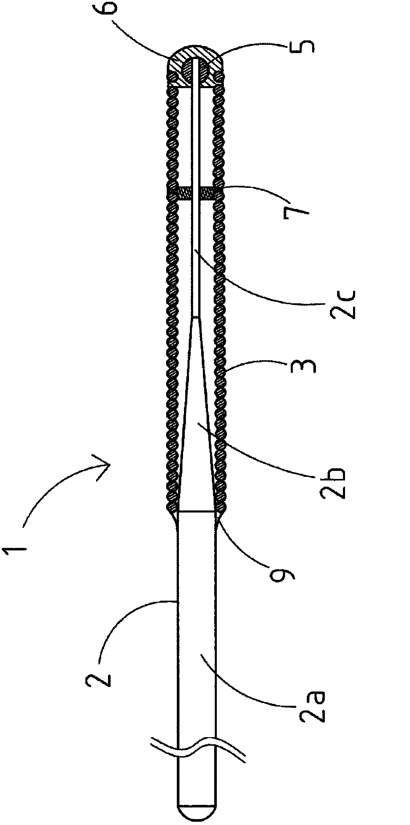
[0050] figure 1 It is an overall view showing the lead wire according to the first embodiment of the present invention.

[0051] For convenience of explanation, in figure 1 In the description, the left side is referred to as a "base end" and the right side is referred to as a "tip end".

[0052] Furthermore, for ease of understanding, the figure 1 The length direction of the lead wire 1 is shortened, and the overall size of the lead wire 1 is different from the actual one in order to schematically illustrate the whole.

[0053] exist figure 1 Among them, the lead wire 1 includes a mandrel 2 and a coil member 3 covering the front end of the mandrel 2 .

[0054]The mandrel 2 includes a large diameter portion 2a, a tapered portion 2b located at the front end of the large diameter portion 2a and decreasing in outer diameter toward the front end, and a small diameter portion 2c located at the front end of the tapered portion 2b.

[0055] A swollen portion 5 is provided on the ...

no. 2 approach

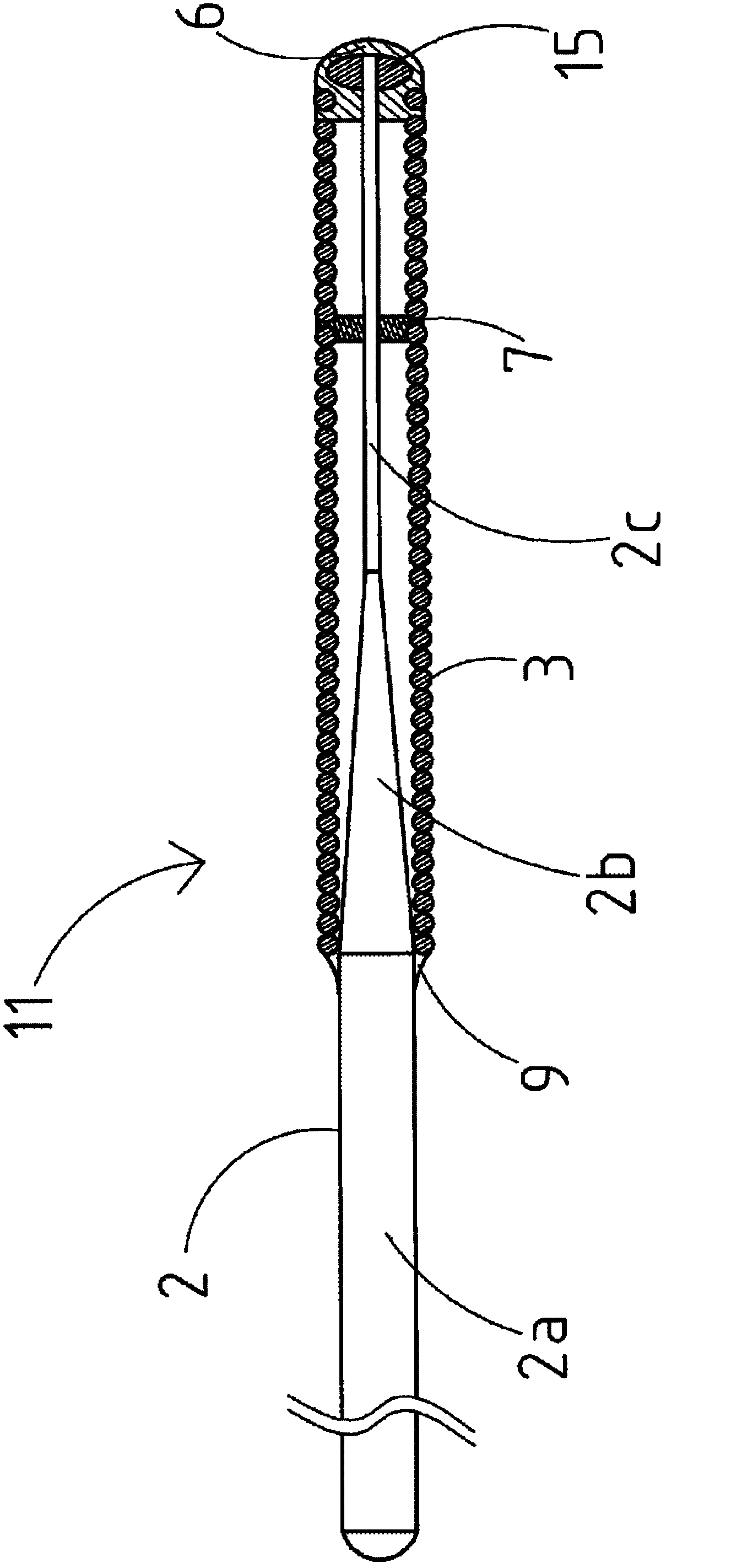
[0098] Next, use figure 2 , the lead wire 11 of the second embodiment will be described focusing on the differences from the first embodiment. In the drawings, the same parts as those of the first embodiment are given the same reference numerals.

[0099] In addition, for ease of understanding, figure 2 Here, the length direction of the lead wire 11 is shortened, and in order to schematically illustrate the entirety of the lead wire 11 , the overall size of the lead wire 11 is different from the actual one.

[0100] exist figure 2 Among them, the wire 11 has the same basic structure as the wire 1 , except that the outer diameter of the bulge 15 is larger than the inner diameter of the coil of the coil member 3 .

[0101] Since the outer diameter of the bulging portion 15 of the lead wire 11 is larger than the coil inner diameter of the coil member 3, the coil member 3 can be further prevented from falling off the mandrel 2, thereby further improving the safety of the lea...

no. 3 approach

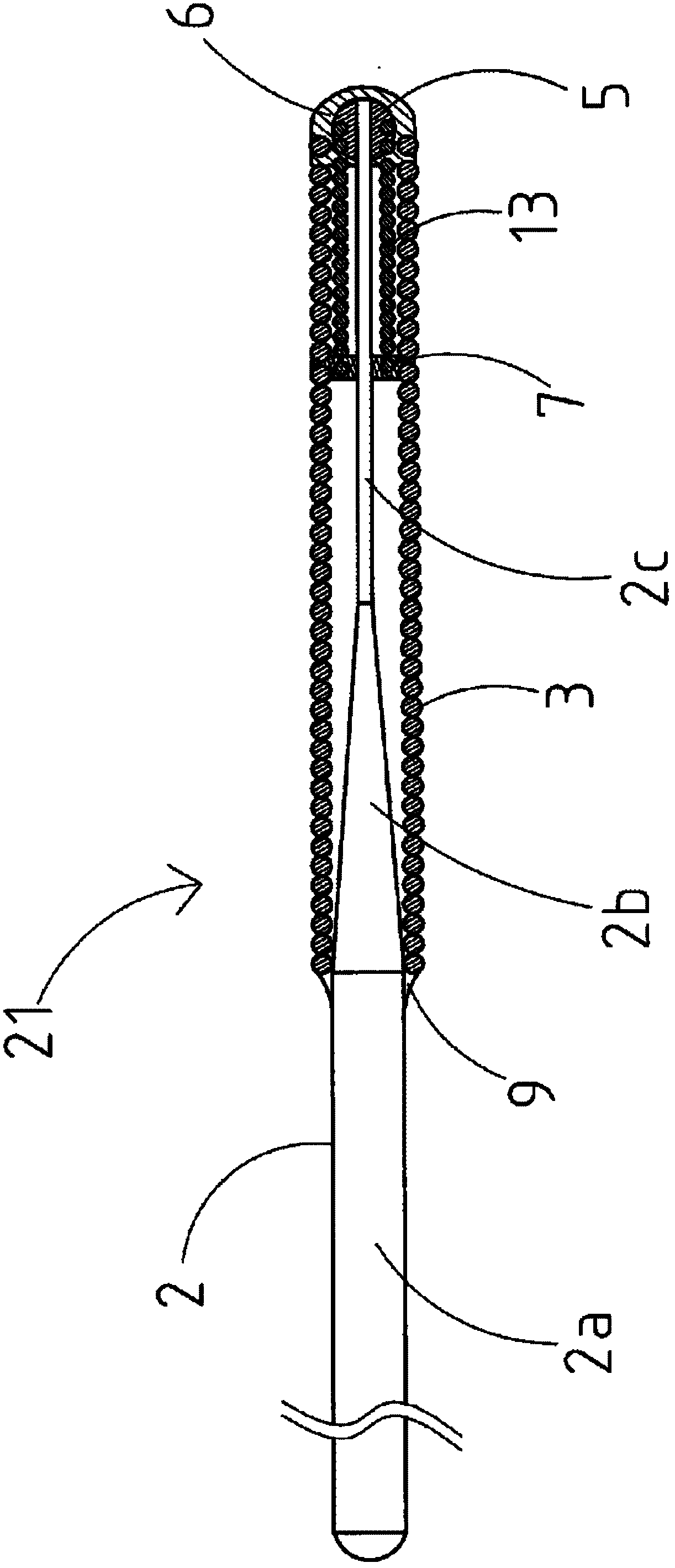
[0105] Next, use image 3 , the lead wire 21 of the third embodiment will be described focusing on the differences from the first embodiment. In the drawings, the same parts as those of the first embodiment are given the same reference numerals.

[0106] In addition, for ease of understanding, image 3 The length direction of the lead wire 21 is shortened, and in order to schematically illustrate the entirety of the lead wire 21, the overall size of the lead wire 21 is different from the actual one.

[0107] exist image 3 Among them, the lead wire 21 includes: a mandrel 2; a coil member 3 covering the front end of the mandrel 2; The distal end of the small-diameter portion 2c of The front end of the coil member 3 is fixedly connected to the front end of the mandrel 2 and the front end of the inner coil member 13 through the fixed connection portion 6 so that the fixed connection portion 6 covers the bulge portion 5 . Further, the proximal end of the coil member 3 is fixe...


PUM


Abstract

An object of the present invention is to provide a highly safe guidewire 1 by increasing the bonding strength between a core shaft 2 and a coiled body 3 of the guidewire 1. The guidewire 1 includes the core shaft 2, and the coiled body 3 wound around the outer circumferential surface of the core shaft 2. A bulged portion 5 is provided at the tip portion of the core shaft 2. The front end of the coiled body 3 is bonded to the front end of the core shaft 2 with a bonding portion 6. The bonding portion 6 is provided to enclose the bulged portion 5 provided at the tip portion of the core shaft 2.

Description

technical field [0001] The present invention relates to a wire. Background technique [0002] Conventionally, various guide wires have been proposed for inserting into tubular organs such as blood vessels, digestive tracts, and urethra, or in vivo tissues, and for guiding medical devices and the like to a target site. [0003] For example, Patent Document 1 (Japanese Unexamined Patent Application Publication No. Hei 6-81547) describes a lead wire provided with a head at the tip of a core wire, and the head and the tip of the coil are fixedly connected by metal solder. [0004] In addition, Patent Document 2 (Japanese Patent Laid-Open Publication No. 2010-214054) describes a lead wire in which a core wire and a front end portion of a coil spring are fixedly connected by Au—Sn based solder, and inside the lead wire Filled with resin. [0005] However, in the lead wire described in Patent Document 1, since the fixed connection portion on the head side of the head and the coil...

Claims


Application Information

Patent Timeline
Patent Type & Authority Applications(China)
IPC IPC(8): A61M25/00A61M25/09
CPCA61M2025/09108A61M2025/09175A61M2025/09083A61M25/09
Inventor 宫田尚彦西岸诚槙英昭小池忠裕金沢祐弥
Owner ASAHI INTECC CO LTD
Why Eureka
Try Eureka