Battery box locking mechanism, battery box and manipulator

A box lock and battery technology, applied in manipulators, program-controlled manipulators, electric power devices, etc., can solve the problems of cumbersome unlocking process, easy battery, complex structure, etc., to ensure reliability, strong practicability, and improve work efficiency Effect

Active Publication Date: 2012-08-01
STATE GRID CORP OF CHINA +2
View PDF9 Cites 30 Cited by
  • Summary
  • Abstract
  • Description
  • Claims
  • Application Information

AI Technical Summary

Problems solved by technology

[0009] The purpose of the present invention is to provide a battery box locking mechanism, a battery box and a manipulator to solve the technical problems of the existing battery box locking mechanism with complex structure, cumbersome unlocking process and easy occurrence of battery throwing off

Method used


Image

  • Battery box locking mechanism, battery box and manipulator
  • Battery box locking mechanism, battery box and manipulator
  • Battery box locking mechanism, battery box and manipulator

Examples


Embodiment Construction

[0030] The embodiments of the present invention will be described in detail below with reference to the accompanying drawings, but the present invention can be implemented in many different ways defined and covered by the claims.

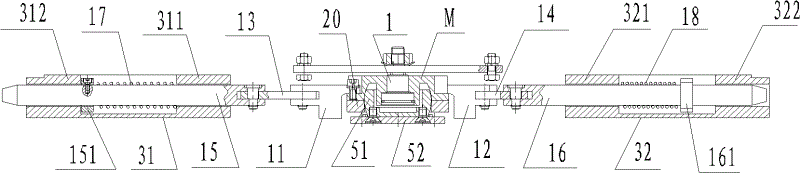
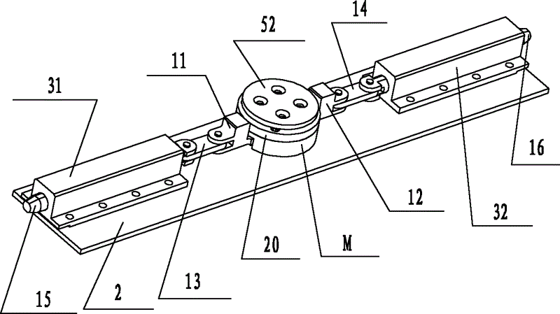
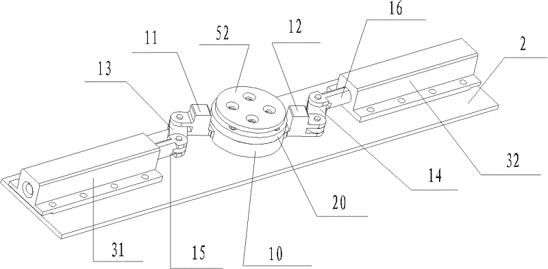
[0031] figure 1 It is a schematic diagram of the cross-sectional structure of the battery box locking mechanism in a preferred embodiment of the present invention, such as figure 1 shown. The present invention provides a locking mechanism for a battery box, comprising: a turntable M rotating around a rotating shaft 1; along the radial direction of the turntable M, a first turntable arm 11 and a second turntable arm 12 protruding symmetrically in opposite directions; The extended end of the turntable arm 11 is hinged with a first link 13, and the extended end of the second turntable arm 12 is hinged with a second link 14; the other end of the first link 13 is hinged with a first lock bar 15, the second The other end of the connecting rod 14 is hing...


PUM


Abstract

The invention provides a battery box locking mechanism, a battery box and a manipulator. The battery box locking mechanism comprises a turntable rotating around a rotating shaft and telescoping mechanisms articulated with articulating parts, wherein the articulating parts which are far away from the rotating shaft at a certain distance are arranged on the turntable; and each telescoping mechanism comprises a connecting rod with a first end articulated with each articulating part, and a lock rod articulated with a second end of each connecting rod, and the articulating parts and the telescoping mechanisms are symmetrically arranged with one another by taking the rotating shaft as the center. The battery box locking mechanism of the invention is high in reliability by adopting a mechanical lock mode, so that the misoperation can be avoided; and the dead point position of the two telescoping mechanisms has the self-locking performance, so that the locking reliability of a mechanical lock can be guaranteed, and the inner box of the battery can be prevented from throwing off effectively. Meanwhile, not only can the automatic unlocking and locking be carried out by the manipulator, but also the manual unlocking and locking can be carried out by manual operation, so that the invention is higher in practical applicability, and the battery reloading work efficiency can be preferably improved.

Description

technical field [0001] The invention relates to the field of electric vehicles, in particular to a battery box locking mechanism and a battery box. In addition, the present invention also relates to a manipulator that cooperates with the above battery box locking mechanism. Background technique [0002] At present, the battery life of electric vehicles is mainly realized by charging the whole vehicle and replacing the battery. Among them, replacing the battery is to regard the battery as a detachable device, and realize it by separating the car body, centralized charging, and quick replacement. However, usually the battery is fixed in the body of the electric vehicle through a locking mechanism, and in order to improve the reliability and safety of the electric vehicle, the locking mechanism for locking the battery needs to meet the following technical requirements: [0003] First, high reliability, that is, once the battery is locked, there will be no problems such as batt...

Claims


Application Information

Patent Timeline
Patent Type & Authority Applications(China)
IPC IPC(8): B60S5/06B25J9/08B25J15/06
Inventor 陈强杭洋张春峰杨兵锋卢海滨梁飞宇
Owner STATE GRID CORP OF CHINA
Why Eureka
Try Eureka